


2-8
2-3-2 Connecting the main circuit and ground terminals
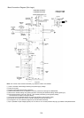
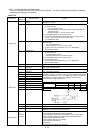
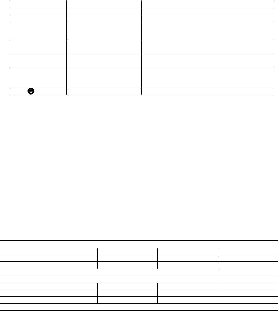
Table 2-3-1 Functions of main circuit terminals and ground terminals
Symbol Terminal name Description
L1/R, L2/S, L3/T Main circuit power terminal Connects a 3-phase power supply.
U, V, W Inverter output terminal Connects a 3-phase motor.
R0, T0
Auxiliary control-power
input terminal
Connects a backup AC power supply to the
control circuit. (Not supported for inverter of 1HP
or less)
P1, P (+)
DC reactor connecting
terminal
Connects the optional power-factor correcting DC
reactor.
P (+), DB
External braking resistor
connecting terminal
Connects the optional external braking resistor.
(For inverter of 10HP or less)
P (+), N (-) DC link circuit terminal
Supplies DC link circuit voltage to the external
braking unit (option) or power regeneration unit
(option).
G Inverter ground terminal Grounds the inverter chassis (case) to the earth.
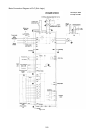
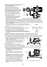
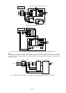
(1) Main circuit power terminals (L1/R, L2/S, L3/T)
① Connect these terminals to the power supply via a molded-case circuit breaker or a ground-fault circuit
interrupter for circuit (wiring) protection. Phase-sequence matching is unnecessary.
② To ensure safety, a magnetic contactor should be connected to disconnect the inverter from the power
supply when the inverter protective function activates.
③ Use control circuit terminal FWD/REV or the RUN/STOP key on the keypad panel to start or stop the
inverter. The main circuit power should be used to start or stop the inverter only if absolutely necessary
and then should not be used more than once every hour.
④ If you need to connect these terminals to a single-phase power supply, please contact the factory.
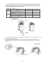
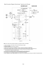
(2) Inverter output terminals (U, V, W)
① Connect these terminals to a 3-phase motor in the correct phase sequence. If the direction of motor
rotation is incorrect, exchange any two of the U, V, and W phases.
② Do not connect a power factor correction capacitor or surge absorber to the inverter output.
③ If the cable from the inverter to the motor is very long, a high-frequency current may be generated by stray
capacitance between the cables and result in an overcurrent trip of the inverter, an increase in leakage
current, or a reduction in current indication precision.
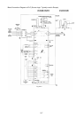
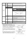
When a motor is driven by a PWM-type drive, the motor terminals may be subject to surge voltage generated
by drive element switching. If the motor cable (with 460V series motors, in particular) is particularly long,
surge voltage will deteriorate motor insulation. To prevent this, use the following guidelines:
Inverters 7.5 HP and larger
Motor Insulation Level 1000V 1300V 1600V
460 VAC Input Voltage 66 ft (20 m) 328 ft (100 m) 1312 ft (400 m) *
230 VAC Input Voltage 1312 ft (400 m) * 1312 ft (400 m) * 1312 ft (400 m) *
Inverters 5 HP and smaller
Motor Insulation Level 1000V 1300V 1600V
460 VAC Input Voltage 66 ft (20 m) 165 ft (50 m) * 165 ft (50 m) *
230 VAC Input Voltage 328 ft (100 m) * 328 ft (100 m) * 328 ft (100 m) *
* For this case the cable length is determined by secondary effects and not voltage spiking.
Note: When a motor protective thermal O/L relay is inserted between the inverter and the motor, the thermal
O/L relay may malfunction (particularly in the 460V series), even when the cable length is 165 feet (50m) or
less. To correct, insert a filter or reduce the carrier frequency. (Use function code “F26 Motor sound”.)