


6-1
6. Protective Operation
6-1 List of Protective Operations
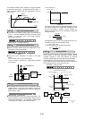
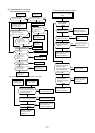
In the event of an abnormality in the inverter, the protective function will activate immediately to trip the inverter, display the
alarm name on the LED monitor, and the motor coasts-to-a stop. For alarm contents, see Section 6.1.1.
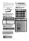
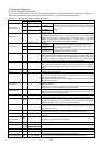
Table 6.6.1 List of alarm displays and protective functions
Keypad panel display
Alarm Name
LED LCD
Contents of operation
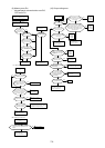
OC1
OC DURING ACC During
acceleration
OC2
OC DURING DEC
During
deceleration
Over current
OC3
OC AT SET SPD
Running at
constant speed
If the inverter output current momentarily exceeds the overcurrent
detection level due to an overcurrent in the motor, or a short-circuit
or a ground fault in the output circuit, the protective function is
activated.
Ground fault
EF
GROUND FAULT
If a ground fault in the inverter output circuit is detected, the protective function is
activated (for 40HP or more only). If a ground fault occurs in an inverter rated at
30HP or less, the inverter is protected by the overcurrent protection. If protection
against personal injury or property damage is required, install a ground-fault
protective relay or earth-leakage circuit breaker separately.
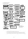
OU1
OV DURING ACC
During
acceleration
OU2
OV DURING DEC
During
deceleration
Overvoltage
OU3
OV AT SET SPD
Running at
constant speed
If the DC link circuit voltage of the main circuit exceeds the
overvoltage detection level (230V series: 400V DC,460V series:
800V DC) due to an increase in the regenerating current from the
motor, the output is shut down.
However, protection against inadvertent overvoltage apply (e.g.,
high-voltage line) may not be provided.
Undervoltage
LU
UNDERVOLTAGE
If the DC link circuit voltage of the main circuit falls below the undervoltage detection
level (230V series: 200V DC,460V series: 400V DC) due to a lowered power supply,
the output is shut down. If function code F14 (Restart after momentary power failure)
is selected, an alarm is not displayed. In addition, if the supply voltage falls to a
level unable to maintain control power, an alarm may not be displayed.
Input open-phase
Lin
PHASE LOSS
If the inverter is driven with any one of the three phases connected to L1/R, L2/S and
L3/T of the main circuit power supply "open", the rectifying diodes or smoothing
capacitors may be damaged, at such time an alarm is issued and the inverter is
tripped.
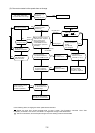
Overheating of heat
sink
OH1
FIN OVERHEAT
If the temperature of the heat sink rises due to a cooling fan failure, etc., the
protective function is activated.
External alarm
OH2
EXT ALARM
If the external alarm contacts of the braking unit, braking resistor or external thermal
O/L relay are connected to the control circuit terminals (THR), this alarm will be
actuated according to contact off signal.
When the PCT thermal protection is activated(H26:1), it operates when the detected
temperature is increased.
Inverter internal
overheating
OH3 HIGH AMB TEMP If the temperature inside the inverter rises due to poor ventilation, etc., the protective
function is activated.
Overcurrent of the terminal 13(20mA or more) due to the short circuit between the
terminal 13 and 11, etc., the protective function is activated.
Overheating of
braking resistor
dbH
DBR OVERHEAT
If electronic thermal O/L relay (for braking resistor) function code F13 is selected, the
protective function is activated to prevent the resistor from burning due to overheating
following frequent use of the braking resistor.
Motor 1 overload
OL1
MOTOR1 OL
The protective function is activated if the motor current exceeds the preset level,
provided that electronic thermal O/L relay 1 function code F10 has been selected.
Motor 2 overload
OL2
MOTOR2 OL
If the second motor current exceeds the preset level when the operation is switched
to drive the second motor, the protective function is activated, provided that
electronic thermal O/L relay 2 of function code A04 is selected.
Inverter overload
OLU
INVERTER OL
If the output current exceeds the rated overload current, the protective function is
activated to provide thermal protection against semiconductor element overheating in
the inverter main circuit.
Blown fuse
FUS
DC FUSE OPEN
If the fuse in the inverter is blown out following a short-circuit or damage to the
internal circuit, the protective function is activated (for 40HP or more only).
Memory error
Er1
MEMORY ERROR
If a memory error occurs, such as missing or invalid data, the protective function is
activated.
Keypad panel
communication
error
Er2
KEYPD COM ERR
If a communication error or interrupt between the keypad panel and control circuit is
detected, the protective function is activated.
CPU error
Er3
CPU ERROR
If an CPU error occurs due to noise, etc., the protective function is activated.
Er4
OPTN COM ERR Option error
Er5
OPTION ERROR
Error when using an optional unit
Forced stop
Er6
OPR PROCD ERR
Error when using the forced stop command
Output wiring error
Er7
TUNING ERROR
If there is an open circuit or a connection error in the inverter output wiring during
performing auto-tuning, the protective function is activated.
RS-485
communication error
Er8
RS-485 COM ERR
If an error occurs when using RS-485, the protective function is activated.