


9-8
9-4 RS-485 Modbus RTU Serial Communications
The serial interface supports operation, configuration and monitoring of inverter functions through an
EIA/RS-485 connection. The serial interface is based on Modbus RTU protocol. This protocol allows the
inverter to function as an RTU slave on an industrial network.
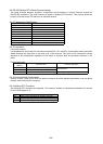
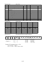
9-4-1 Transmission Specification
Item Specification
Physical level EIA/RS-485
Transmission distance 1600 ft (500 m)
Number of nodes 32 total
Transmission speed 19200, 9600, 4800, 2400 [bits/s]
Transmission mode Half duplex
Transmission protocol Modbus RTU
Character code Binary
Character length 8 bits
Error check CRC
9-4-2 Connection
Connection method
Use shielded wire and connect to the control terminals (DX-, DX+ and SD). A termination resistor should be
added between the data lines on the each end of the network. The value of the termination resistor
depends on the characteristic impedance of the cable. A common value for termination resistors is 120
ohms.
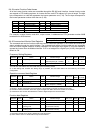
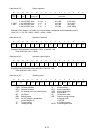
Control terminals
Terminal
marking
Terminal name Function description
DX+ RS-485 communication data (+)
DX- RS-485 communication data (–)
Input/output terminals for RS-485
communication.
SD Cable shield Electrically floating
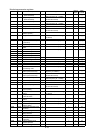
9-4-3 Serial Interface Configuration
Inverter function codes H30 to H39 are used to configure the serial interface parameters, such as device
address, baud rate and error response.
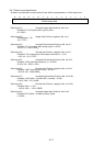
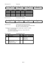
9-4-4 Modbus RTU Functions
The following RTU functions are supported. The maximum number of consecutive parameters for function
03 and 16 messages is 16.
Code Description
03 Read Holding Registers (16 registers maximum)
06 Preset Single Register
16 Preset Multiple Registers (16 registers maximum)