


5-4
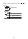
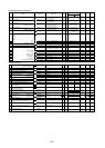
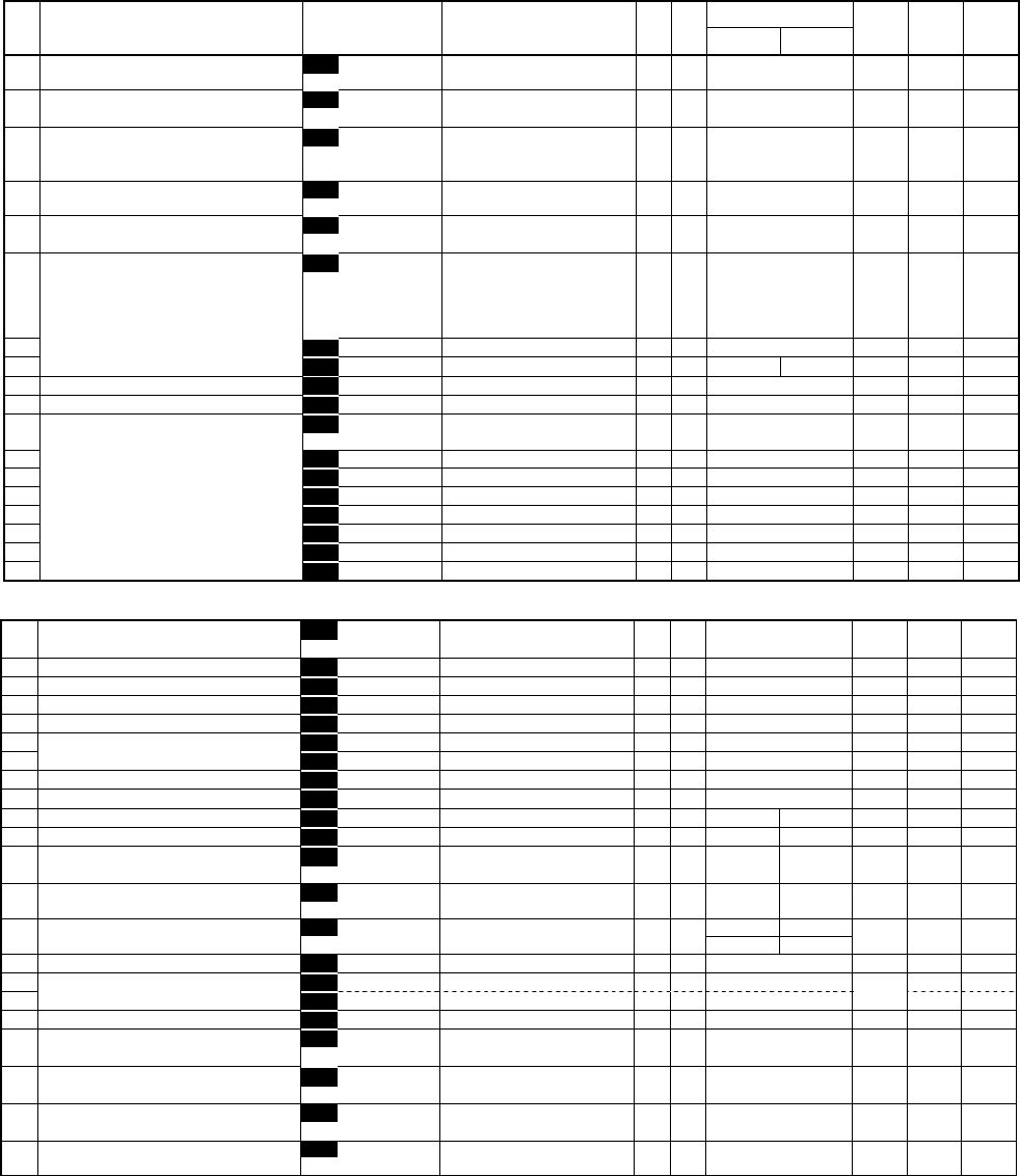
A:Alternative Motor Parameters
Factory setting
Func
No.
NAME LCD Display Setting range Unit
Min.
Unit
-30HP 40HP-
Change
during op
User
Set value
Remark
A01 Maximum frequency 2 A01 MAX Hz-2 G11S: 50 to 400Hz Hz 1 60 NA
P11S: 50 to 120Hz
A02 Base frequency 2 A02 BASE Hz-2 G11S: 25 to 400Hz Hz 1 60 NA
P11S: 25 to 120Hz
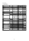
A03 Rated voltage 2 A03 RATED V-2 0: V 1 220:(230V class) NA
(at Base frequency 2 ) 80 to 240V:(230V class) 380:(460V class)
320 to 480V:(460V class)
A04 Maximum voltage 2 A04 MAX V-2 80 to 240V:(230V class) V 1 220:(230V class) NA
(at Base frequency 2) 320 to 480V:(460V class) 380:(460V class)
A05 Torque boost2 A05 TRQ BOOST2 0.0, 0.1 to 20.0 - - G11S:2.0 A
P11S:0.1
A06 Electronic (Select) A06 ELCTRN OL2 0, 1, 2 - - 1 A
thermal
overload
relay for
motor 2
A07 (Level) A07 OL LEVEL2 INV rated current 20%to135% A 0.01 Motor rated current A
A08 (Thermal time constant) A08 TIME CNST2 0.5 to 75.0 min min 0.1 5.0 10.0 A
A09 Torque vector control 2 A09 TRQVECTOR2 0, 1 - - 0 NA
A10 Number of motor-2 poles A10 M2 POLES 2 to 14 poles ploes 2 4 NA
A11 Motor 2 (Capacity) A11 M2-CAP Up to 30HP:0.01 to 60HP HP 0.01 Motor capacity NA
40HP and above:0.01to800HP
A12 (Rated current) A12 M2-Ir 0.00 to 2000A A 0.01 Motor rated current NA
A13 (Tuning) A13 M2 TUN1 0, 1, 2 - - 0 NA
A14 (On-line Tuning) A14 M2 TUN2 0, 1 - - 0 NA
A15 (No-load current) A15 M2-Io 0.00 to 2000A A 0.01 Fuji standard rated value NA
A16 (%R1 setting) A16 M2-%R1 0.00 to 50.00% % 0.01 Fuji standard rated value A
A17 (%X setting) A17 M2-%X 0.00 to 50.00% % 0.01 Fuji standard rated value A
A18 (Slip compensation control 2) A18 SLIP COMP2 0.00 to 15.00Hz Hz 0.01 0.00 A
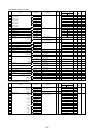
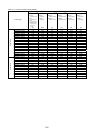
U:User Functions
U01 Maximum compensation frequency U01 USER 01 75 A
during braking torque limit
0 to 65535
- 1
U02 1st S-shape level at acceleration U02 USER 02 1 to 50% % 1 10 NA
U03 2nd S-shape level at acceleration U03 USER 03 1 to 50% % 1 10 NA
U04 1st S-shape level at deceleration U04 USER 04 1 to 50% % 1 10 NA
U05 2nd S-shape level at deceleration U05 USER 05 1 to 50% % 1 10 NA
U08 Main DC link capacitor (Initial value) U08 USER 08 0 to 65535 - 1 xxxx A
U09 (Measured value) U09 USER 09 0 to 65535 - 1 0 A
U10 PC board capacitor powered on time U10 USER 10 0 to 65535h h 1 0 A
U11 Cooling fan operating time U11 USER 11 0 to 65535h h 1 0 A
U13 Magnetize current vibration damping gain U13 USER 13 0 to 32767 - 1 819 410 A
U15 Slip compensation filter time constant U15 USER 15 0 to 32767 - 1 556 546 A
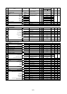
U23 Integral gain of continuous operation U23 USER 23 1738 1000 A
at power failure
0 to 65535
- 1
U24 Proportional gain of continuous U24 USER 24 1024 1000 A
operation at power failure
0 to 65535
- 1
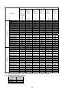
U48 Input phase loss protection U48 USER 48 -75HP 100HP- NA
0, 1, 2
- -
0 1
U49 RS-485 protocol selection U49 USER 49 0, 1 -- 1 NA
U56 Speed agreement (Detection width) U56 USER 56 0 to 50% % 1 10 A
U57 /PG error (Detection timer) U57 USER 57 0.0 to 10.0s s 0.1 0.5
U58 PG error selection U58 USER 58 0, 1 -- 1 NA
U59 Braking-resistor function select(up to 30HP) U59 USER 59 00 NA
Manufacturer's function(40HP or more)
00 to A8(HEX)
- 1
U60 Regeneration avoidance at deceleration U60 USER 60 0 NA
0, 1
- -
U61 Voltage detect offset and gain adjustment U61 USER 61 --30HP:0(Fixed.) 0 A
40HP--:0, 1, 2
- -
U89 Motor overload memory U89 USER 89 0.1 - - 1 A
retention