


5-19
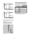
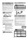
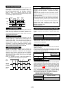
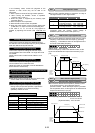
When BX and P24 are connected, inverter output is cut off
immediately and the motor starts to coast-to-stop. An
alarm signal is neither output nor self-held. If BX and
P24 are disconnected when the operation command
(FWD or REV) is on, operation starts at the start
frequency. To use this BX terminal function, assign value
"7" to the target digital input terminal.
When an inverter trip occurs, connecting RST and P24
clears the alarm output (for any fault) ; disconnecting
them clears trip indication and restarts operation. To
use this RST terminal function, assign value "8" to the
target digital input terminal.
Disconnecting THR and P24 during operation cuts off
inverter output (i.e., motor starts to coast-to-stop) and
outputs alarm OH2, which is self-held internally and
cleared by RST input. This function is used to protect an
external brake resistor and other components from
overheating. To use this THR terminal function, assign
value "9" to the target digital input terminal. ON input is
assumed when this terminal function is not set.
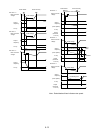
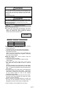
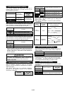
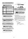
This function is used for jogging (inching) operation to
position a work piece. When JOG and P24 are
connected, the operation is performed with the jogging
frequency set in function code C20 while the operation
command (FWD-P24 or REV-P24) is on. To use this
JOG terminal function, assign value "10" to the target
digital input terminal.
Note: It is possible to change to the JOG operation by
keypad panel when keypad panel operation.
WARNING
- When the JOG command and operation command
(FWD/REV) are input at the same time, it can NOT be
changed to the JOG operation. It operates with setting
frequency.
- When the JOG operation is used, it should be input the
operation command after input the JOG command during
the inverter is STOP.
- When the JOG command and operation command are
input at the same time, the JOG command is assigned to
the "Multistep frequency selection (SS1 to SS8)" and used
it.
- The inverter can NOT be stopped and JOG operation is
continued even JOG command is OFF during JOG
operation. The inverter is deceleration to a stop if the
operation command is OFF.
Accident may result.
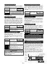
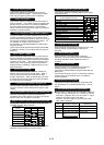
This function switches the frequency setting method set in
function codes F01 and C30 by an external digital input
signal.
Set value input signal
11
Frequency setting method selected
off
F01 FREQ CMD1
on
C30 FREQ CMD2
Note: It can not be used with set value "35"
simultaneously. When the set value "11" and "35" are
selected, "Er6" is displayed.
This function switches motor constants using an external
digital input signal.
This input is effective only when the operation command
to the inverter is off and operation has stopped and does
not apply to the operation at 0Hz.
Set value input signal
12
Motor selected
off
Motor 1
on
Motor 2
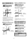
When the external digital input signal is on, DC injection
braking starts when the inverter's output frequency drops
below the frequency preset in function code F20 after the
operation command goes off. (The operation command
goes off when the key is pressed at keypad panel
operation and when both terminals FWD and REV go on
or off at terminal block operation.) The DC injection
braking continues while the digital input signal is on. In
this case, the longer time of the following is selected:
- The time set in function code F22.
- The time which the input signal is set on.
Set value input signal
13
Operation selected
off
No DC injection brake command is given.
on
A DC injection brake command is given.
Forward
rotation
ON
ON
ON
ON
ON
FWD
REV
BX
Output
Frequency
Ignored
Forward
rotation
Forward
rotation
ON
Operation
command
(FWD/REV)
Operation
mode
JOG
Input
OFF
JOG
OPR.
OFF
STOP RUN STOP
ON
RUN
JOG
OPR.
ON
OFF
OFF
STOP
ON
RUN
OFF
STOP
NOR.
OPR.
NOR.
OPR.
ON
RUN
ON
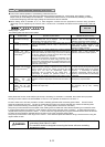
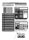
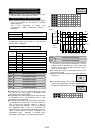
Coast-to-stop command [BX]
External fault [THR]
Jogging operation[JOG]
Motor 2/motor 1 [M1/M2]
DC brake command [DCBRK]
Related function
A01~A18
Alarm reset [RST]
Frequency setting 2/frequency setting 1 [Hz1/Hz2]
STOP