


5-25
Related functions
U08~U11, U59
In the following cases, normal life judgment of the
capacitor in main circuit may not be able to be
performed.
1. When a power is turned off during inverter operation.
2. When cooling fan ON/OFF control is operated.
( function code : H 06= 1)
3. When the power is supplied by the auxiliary input
terminals (R0,T0).
4. When the option card is operated .
5. When RS-485 communication is operated .
6. When the power supply is turned off with digital input
(FWD, REV, X1-X9) of a control terminal being ON.
In the case of "3", "4", "5" and "6", life judgment is
enabled by adjusting the function both code:U08 and
U09.
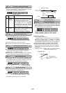
This function is same as Frequency detection [FDT1],
the detection level of the output frequency and hysteresis
width are determined by E36 and E32.
This function outputs an ON signal when the output
current exceeds “E37 OL2 LEVEL” for longer than “E35
OL TIMER”.
NOTE) This function is valid for both of Motor 1 and
Motor 2.
This function outputs an ON signal when the input
current of terminal C1 is less than 2mA.
(When AIO option is connected, it can be detected the
disconnection of C2 terminal.)
The above functions are set for OPC-G11S-PG / PG2
or PGA. Refer to each instruction manual.
The turning on signal is output by continuing the
limiting action(Torque limit operation, regeneration
avoidance operation and overcurrent limiting
operation) of 20ms or more.
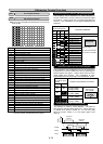
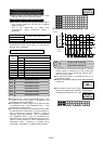
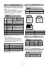
Setting at factory shipment
Digital input
Set value Description
Terminal Y1
0
Operating [RUN]
Terminal Y2
1
Frequency arrival [FAR]
Terminal Y3
2
Frequency detection [FDT]
Terminal Y4
7
Overload early warning [OL1]
Terminal Y5
10
Ready output [RDY]
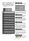
This function specifies whether to excite the Y5 relay at
“ON signal mode” or “OFF signal mode”.
Set value Operation
0 At “OFF signal mode” Y5A - Y5C: OFF
At “ON signal mode” Y5A - Y5C: ON
1 At “OFF signal mode” Y5A - Y5C: ON
At “ON signal mode” Y5A - Y5C: OFF
When the set value is "1", contacts Y5A and Y5C are
connected when the inverter control voltage is
established (about one second after power on).
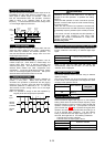
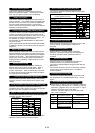
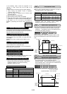
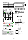
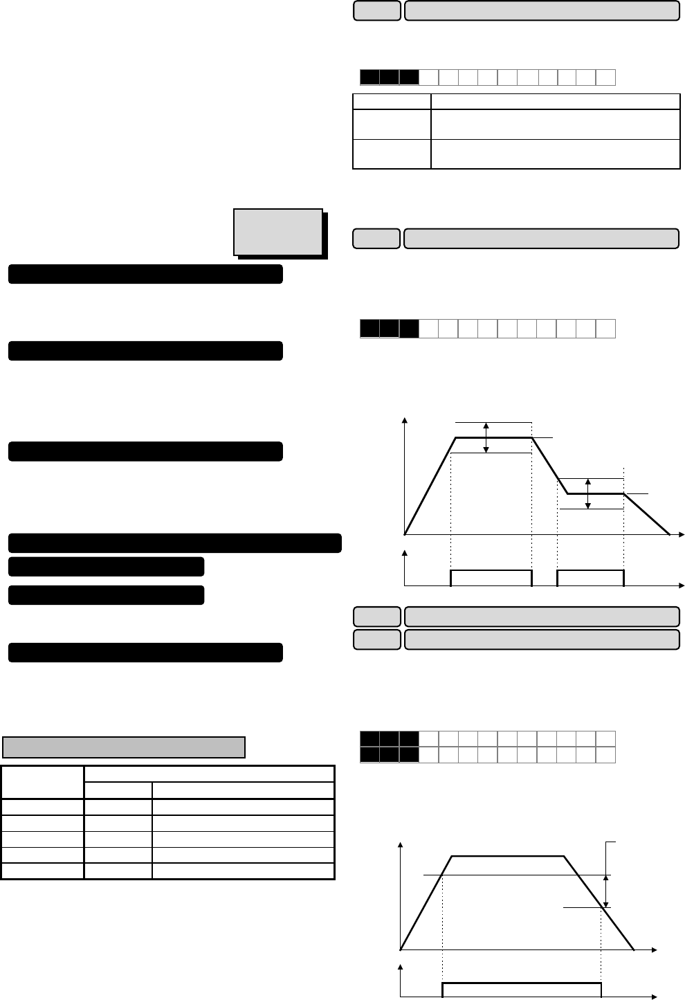
This function adjusts the detection width when the output
frequency is the same as the set frequency (operating
frequency). The detection width can be adjusted from 0
to ±10 Hz of the setting frequency.
Setting range: 0.0 to 10.0 Hz
When the frequency is within the detection width, an ON
signal can be selected and output from terminals [Y1] to
[Y5].
Output frequency
Frequency
detection
signal
(terminals
Y1 to Y5)
+Detection width
-Detection width
Set frequency
+Detection width
-Detection width
Set frequency
Time
ONON
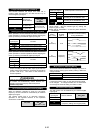
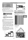
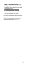
This function determines the operation (detection) level
of the output frequency and hysteresis width for
operation release. When the output frequency exceeds
the set operation level, an ON signal can be selected and
output from terminals [Y1] to [Y5].
Setting range(Operation level) : G11S: 0 to 400 Hz
P11S: 0 to 120 Hz
(Hysteresis width) : 0.0 to 30.0 Hz
Output frequency
Frequency
detection
signal
(terminals
Y1 to Y5)
Hysteresis width
Operation level
Release level
Time
ON
Set frequency
E30 FAR function signal (Hysteresis)
E 3 0 F A R H Y S T R
E32 FDT1 function signal (Hysteresis)
E31 FDT1 function signal (Level)
Settings when shipped from the factory
2nd Freq. level detection [FDT2]
2nd OL level early warning [OL2]
Terminal C1 off signal [C1OFF]
E 3 1 F D T 1 L E V E L
E 3 2 F D T H Y S T R
E25 Y5 Ry operation mode
E 2 5 Y5RY M O D E
Synchronization completed by synchronous operation card [SY]
Speed agreement signal [DSAG]
PG error signal [PG-ABN]
Torque limiting (Signal with delay) [TL2]