


5-18
ON
ON
ON ON
ON
ON
FWD
REV
HLD
Output
frequency
Forward
rotation
Reverse
rotation
Ignore
d
Each function of digital input terminals X1 to X9 can be
set as codes.
Set value
Function
0,1,2,3
Multistep frequency selection (1 to 15 steps) [SS1],[SS2],[SS4],[SS8]
4,5
Acceleration and deceleration time selection (3 steps) [RT1],[RT2]
6
Self-hold selection [HLD]
7
Coast-to-stop command [BX]
8
Alarm reset [RST]
9
External alarm [THR]
10
Jogging [JOG]
11
Frequency setting 2/frequency setting 1 [Hz2/Hz1]
12
Motor 2/motor 1 [M2/M1]
13
DC injection brake command [DCBRK]
14
Torque limit 2/torque limit 1 [TL2/TL1]
15
Switching operation from line to inverter (50Hz) [SW50]
16
Switching operation from line to inverter (60Hz) [SW60]
17
UP command [UP]
18
DOWN command [DOWN]
19
Edit permission command (data change permission) [WE-KP]
20
PID control cancellation [Hz/PID]
21
Forward/inverse switching (terminals 12 and C1) [IVS]
22
Interlock (52-2) [IL]
23
Torque control cancellation [Hz/TRQ]
24
Link operation selection (Standard:RS-485, Option: BUS) [LE]
25
Universal DI [U-DI]
26
Start characteristics selection [STM]
27
PG-SY enable ( Option ) [PG/Hz]
28
Synchronization command ( Option ) [SYC]
29
Zero speed command with PG option [ZERO]
30
Forced stop command [STOP1]
31
Forced stop command with Deceleration time 4 [STOP2]
32
Pre-exiting command with PG option [EXITE]
33
Line speed control Cancellation [Hz/LSC]
34
Line speed frequency memory [LSC-HLD]
35
Frequency setting 1 / Frequency setting 2 [Hz1/Hz2]
Note: Data numbers which are not set in the functions
from E01 to E09, are assumed to be inactive.
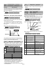
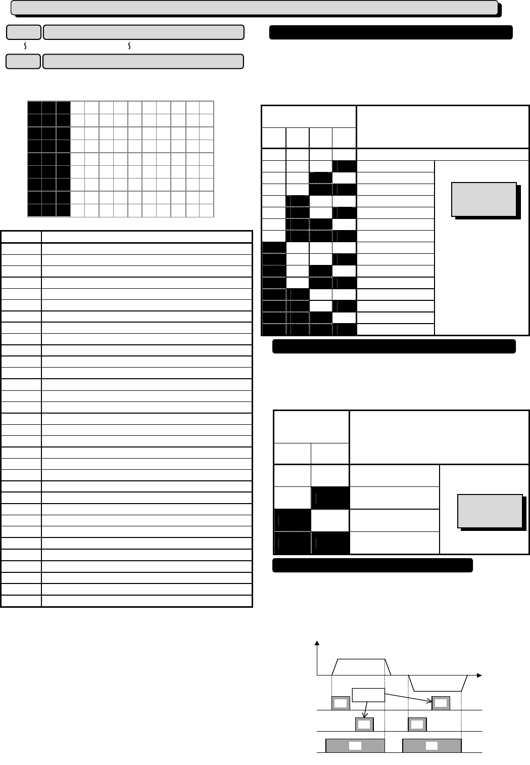
The frequency can be switched to a preset frequency in
function codes C05 to C19 by switching the external digital
input signal. Assign values 0 to 3 to the target digital input
terminal. The combination of input signals determines the
frequency.
Combination of set
value input signals
3
[SS8]
2
[SS4]
1
[SS2]
0
[SS1]
Frequency selected
off off off off
Assigned by F01 or C30
off off off on
C05 MULTI Hz-1
off off on off
C06 MULTI Hz-2
off off on on
C07 MULTI Hz-3
off on off off
C08 MULTI Hz-4
off on off on
C09 MULTI Hz-5
off on on off
C10 MULTI Hz-6
off on on on
C11 MULTI Hz-7
on off off off
C12 MULTI Hz-8
on off off on
C13 MULTI Hz-9
on off on off
C14 MULTI Hz-10
on off on on
C15 MULTI Hz-11
on on off off
C16 MULTI Hz-12
on on off on
C17 MULTI Hz-13
on on on off
C18 MULTI Hz-14
on on on on
C19 MULTI Hz-15
Setting range
G11S:0.00 to 400.00Hz
P11S:0.00 to 120.00Hz
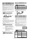
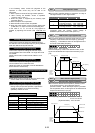
The acceleration and deceleration time can be switched to
a preset time in function codes E10 to E15 by switching the
external digital input signal. Assign values 4 and 5 to the
target digital input terminal. The combination of input
signals determines the acceleration and deceleration times.
Combination of
set value input
signals
5
[RT2]
4
[RT1]
Acceleration and deceleration times selected
off off
F07 ACC TIME1
F08 DEC TIME1
off on
E10 ACC TIME2
E11 DEC TIME2
on off
E12 ACC TIME3
E13 DEC TIME3
on on
E14 ACC TIME4
E15 DEC TIME4
Setting range
0.01 to 3600s
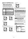
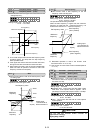
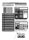
This selection is used for 3-wire operation. The FWD or
REV signal is self-held when [HLD] is on, and the self-hold
is cleared when [HLD] is turned off. To use this [HLD]
terminal function, assign 6 to the target digital input
terminal.
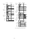
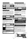
E 0 1 X 1 F U N C
E 0 2 X 2 F U N C
E 0 3 X 3 F U N C
E 0 4 X 4 F U N C
E 0 5 X 5 F U N C
E 0 6 X 6 F U N C
E 0 7 X 7 F U N C
E 0 8 X 8 F U N C
E 0 9 X 9 F U N C
E:Extension Terminal Functions
E01
X1 Terminal function
E09
X9 Terminal function
Multistep frequency selection [SS1][SS2][SS4][SS8]
Acceleration and deceleration time selection [RT1][RT2]
Related function
C05 to C19
Related function
F07~F08
E10~E15
3-wire operation stop command [HLD]