


5-46
△
!
CAUTION
◆Set the function code both “ F13” and “U59 ” before
operating the inverter, and don’t change the functions
during operation. The integrated thermal data are
cleared immediately, when function code “ F13” or
“U59 ” are changed. The overheat protection of
resistor becomes invalid. When the function code
“ F13” or “U59 ” are changed in the state where
temperature rose, the overheat protection of resistor
becomes invalid, too.
◆As there is a possibility of damaging the inverter, the
resistor value less than standard applied value should
not be available.
◆Make into one kind the resistor used as combination
conditions for a braking resistor, and connect it so that
the electric power is consumed equally in each
resistor.
◆When the resistor which is instead of DB***-2C/4C are
used as External braking resistor, function code F13
should be set to “0”.
◆ When resistor values less than Standard applied
resistor value is set to the function code, regeneration
operation is invalid. OU alarm will be occurred.
◆If connection of resistor and setting value of resistor is
not corresponded, there is a possibility of damaging
the resistor and the inverter.
Failure may result.
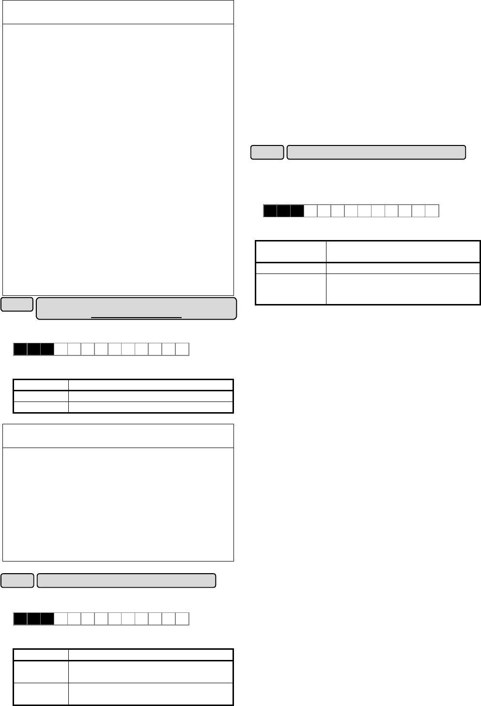
Function for manufacturer
[40HP or more is corresponded]
U59
This function is available to release the overheating alarm
(OH1) at the DC fan broken.
U 5 9 U S E R 5 9
Set value : 00, 01
Set value Operation
00 OH1 alarm at DC fan broken
01 No alarm at DC fan broken
△
!
CAUTION
◆It causes overheating trip (OH1,OH3) in the inverter,
and the life time decrease such as electrolytic
capacitors on the PCB in the unit by a partial rise
temperature, and there is a possibility to the worst unit
damage when left with the DC fan for an internal stir
stops.
Be sure that set it to the fan exchange and the factory
setting value again promptly after the DC fan for an
internal stir stops. (Contact the fan exchange
procedure Fuji Electric.)
Failure may result.
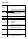
Regeneration avoidance at decelerationU60
◆This function is available, when torque limit (brake) of
F41( or E17) is set to “0%”.
U 6 0 U S E R 6 0
Set value : 0, 1
Set value Operation
0
Torque limit operation
(for high response use)
1
OU alarm avoidance operation
(
for only deceleration or Large inertia use
)
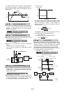
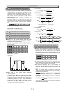
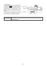
◆If function code U60 is set to “0”, braking torque is kept
to about “0%” under acceleration, deceleration,
constant speed state. Output frequency is controlled in
correspond to the rapid change in motor load to
prevent OU alarm. Deceleration time becomes longer
than the set deceleration time (F08).
◆In case of setting value U60:1, Compared with setting
value "0", it controls not to perform torque limit
operation only at the deceleration time, but to prevent
the rise of the DC voltage of the main circuit, and
avoid OU alarm.
At this time, although deceleration time becomes
longer than a setting value of F08, it becomes shorter
than setting value"0" of U60. It may occur OU alarm, if
load changes rapidly during deceleration.
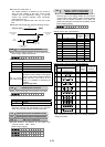
Voltage detect offset and gain adjustmentU61
◆40HP or more :
It adjusts, only when a print board is replaced by
maintenance, etc. If not necessary, do not use this
function.
U 6 1 U S E R 6 1
Set value : 0, 1, 2
Inverter
capacity
Operation
30HP or less 0 : Inactive(fixed)
40HP or more
0 : Inactive
1 : Voltage detect offset adjustment
2 : Voltage detect gain adjustment
◆Set the function code in the following procedure.
If the inverter are operated without this adjustment
after replacing the PC board, normal operation may
not be able to be performed.
(Offset adjustment)
1) Confirm that the main power supply is turned ON,
the motor wiring are connected and the motor has
stopped (inverter operation command is OFF).
2) When the data of U61 is changed to "1", and the
FUNC/DATA key is ON, the offset self adjustment is
started. The display of “storing" of the keypad
panel disappears several seconds later. When the
set value returns to "0", adjustment is completed.
If the main power supply is turned OFF, while
outputting alarm, motor is driving, coast-to-stop
command(BX) is ON and this adjustment is started,
the inverter becomes “Er7:TUNING ERROR".
In this case, start the adjustment after removing the
above-mentioned factor.
(Gain adjustment)
1) Drive the motor in an arbitrary frequency of about
10 to 60Hz(However, constant speed) after
executing the above-mentioned offset
adjustment.(U61:1)
At this time, gain adjustment is available unrelated
to the load state.
2) When the data of U61 is changed to "2", and the
FUNC/DATA key is ON, the gain self adjustment is
started. The display of “storing" of the keypad
panel disappears several seconds to 30 seconds
later. When the set value returns to "0", adjustment
is completed.
If inverter is not operated, this adjustment is not
available.