


2-11
M
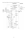
CN RX TX
L1/R
L2/S
L3/T
Magnetic
contactor
Noise filter
MCCB
Power supply
R0
T0
P1
P(+)
Jum
p
er (not su
pp
lied for inverter of 75kW or more)
Fan
U
V
W
N(-)
C
F
Inverter
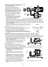
CN RX TX
R0
T0
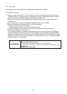
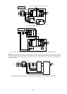
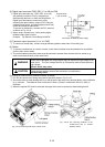
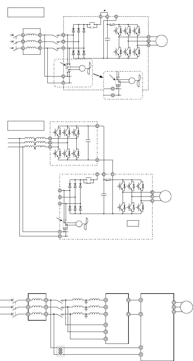
When switched to DC power input mode
+
30kW or more
Fig. 2-3-9 Fan power switching
30kW or more
M
P1
P(+)
N(-)
CN RX TX
+
C
L1/R
L2/S
L3/T
R0
T0
Fan
U
V
W
F
Inverter
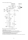
Switch CNRXTX to the R0-T0 side.
+
Power supply
R
S
T
P(+)
N(-)
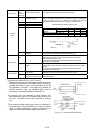
PWM converter
C
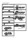
Fig. 2-3-10A Example of connection by combination with power regeneration converter(40HP or more)
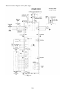
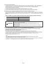
Note:
To connect the power regeneration converter to an inverter of 30HP or less, do not connect the power supply directly to the auxiliary control-power input
terminals (R0 and T0) of the inverter. However, if such a connection is required, insulate these input terminals from the main power of the power
regeneration converter with an insulation transformer. The connection example of a power regeneration unit is provided in the "Power Regeneration
Unit Instruction Manual".
Magnetic
contactor
Noise filter
MCCB or RCD
Power supply
Insulation Transformer
L1/R
L2/S
L3/T
R1
S1
T1
RHC series
R0
T0
L1/R
L3/T
FRN-G11S
U
V
W
M
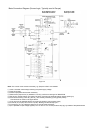
Fig. 2-3-10B Example of connection by combination with power regeneration converter (30HP or less)
40HP or more
Jumper (not supplied for inverter of 100HP or more)
40HP or more