


9-9
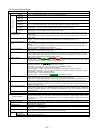
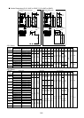
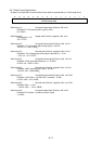
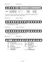
9-4-5 Inverter Function Code Access
All of the inverter function codes are accessible through the RS-485 serial interface. Inverter function codes
are mapped to RTU holding registers. An inverter function code RTU address is 2 bytes in length. The high
byte corresponds to a code that represents the inverter parameter sort (F–M). The low byte corresponds to
the inverter parameter number within the sort (0 -99).
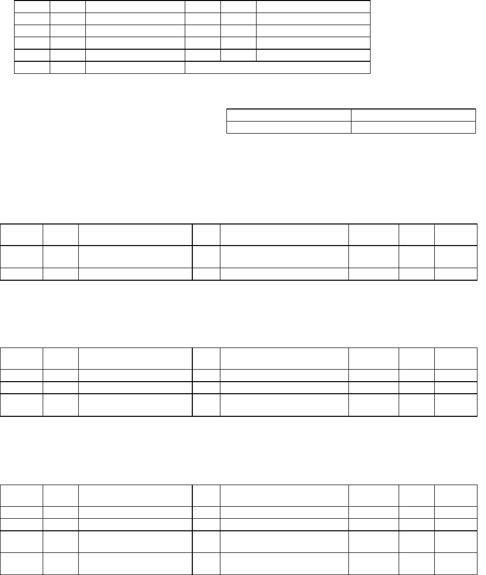
Code Sort Name Code Sort Name
0 F Basic function 5 A Motor 2 function
1 E Terminal function 6 o Option function
2 C Control function 7 S Command/function data
3 P Motor 1 function 8 M Monitor data
4 H High level function
For example, inverter function code M11, output current, is addressed as RTU parameter number 080B
hexadecimal or 2059 decimal.
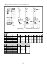
9-4-6 Command and Monitor Data Registers
The command and monitor function codes are used to control the operation of the inverter and monitor the
status variables through the serial interface. The command and monitor function codes are not accessible
from the inverter keypad interface. Inverter parameter H30 and digital input signal LE must be enabled to
operate the inverter from the Modbus interface. If LE is not assigned to a digital input (X1-X9), the signal will
default to ON.
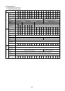
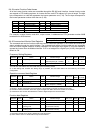
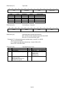
Frequency Setting Registers
Address Code Name Unit Variable Range Min. unit
Read/
Write
Data
Format
1793 S01 Frequency command -
-20000–20000
(max. frequency at ± 20000) 1 R/W 2
1797 S05 Frequency command Hz 0.00–400.00 0.01 R/W 5
Note:
1) If both S01 and S05 are set, the inverter will ignore the setting of S05.
2) A data setting that exceeds the setting range is possible, but the actual action will be limited by the inverter
configuration.
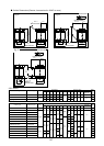
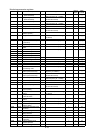
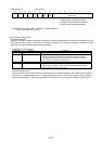
Operation command data Registers
Address Code Name Unit Variable Range Min. unit
Read/
Write
Data
Format
1798 S06 Operation command - Refer to the data format [14] - R/W 14
1799 S07 Universal Do - Refer to the data format [15] - R/W 15
1804 S12 Universal Ao -
-20000–20000
(100% output at ± 20000 )
1 R/W 2
Note:
1) Since X1–X9 are configurable input commands, it is necessary to set the functions by E01–E09.
2) The alarm reset is executed, when RST signal changes from ON to OFF even if there are no alarms.
3) Universal Do is a function that utilizes the inverter’s digital outputs via communication.
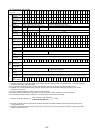
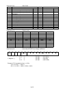
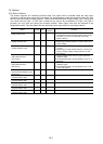
Function data Registers
Address Code Name Unit Variable Range Min. unit
Read/
Write
Data
Format
1800 S08 Acceleration time F07 s
0.1–3600.0
0.1 R/W 3
1801 S09 Deceleration time F08 s
0.1–3600.0
0.1 R/W 3
1802 S10 Torque limit level 1
(driving) F40
%
20.00 –200.00, 999
(P11S:20.00-150.00)
1.00 R/W 5
1803 S11 Torque limit level 2
(braking) F41
%
0.00, 20.00–200.00, 999
(P11S:20.00-150.00)
1.00 R/W 5
Note:
1) The writing of data out of range is treated as out of range error.
2) Use a value of 7FFF
H
to enter 999 for torque limit functions.
high byte low byte
inverter parameter sort code inverter parameter number