


5-36
This function smoothly starts the motor which is coasting
after a momentary power failure or after the motor has
been subject to external force, without stopping motor.
At startup, this function detects the motor speed and
outputs the corresponding frequency, thereby enabling a
shock-free motor startup. Although the normal startup
method is used, when the coasting speed of the motor is
120 Hz or more as an inverter frequency, when the value
set to "F03 Maximum frequency," exceeds the value set to
"F15 Frequency limiter (upper limit)." and when the
coasting speed is less than 5 Hz as an inverter frequency.
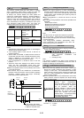
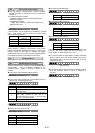
H 0 9 S T A R T M O D E
Set value 0,1,2
Set value STM
Restart after a
momentary power
failure or
Line-to-inverter
switching
Other
operation
0
Inactive
(normal starting)
1
Active
(smoothly starting)
Inactive
2
OFF /
not selected
Active
any value ON Active
STM: Start characteristics selection signal(E01 to E09: 26)
NOTE:
-1: Automatically restart when overcurrent or overvoltage is
detected during smoothly starts.
-2: The coasting speed is used 100 Hz or less as an
inverter frequency.
-3: When H09:2 or STM:ON, it needs the time more than
normal start even the motor is STOP because the motor
speed is detected on ALL situation. And it may be
rotated the motor when the load is too small.
-4: Auto tuning(P04/A13: 2) should be done to use this
function.
-5: When the used motor slippage is too differ from FUJI
motor, the "Slip compensation control (P09, A18)"
should be set. The characteristics may not be satisfied.
When the operation above is to be problem, this function
is not used (inactive).
This function may not be satisfied the characteristics
because of the load condition, motor constant, operating
frequency, coasting speed, wire length, momentary
power failure time or external factor.
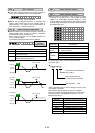
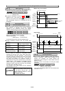
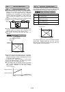
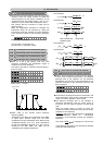
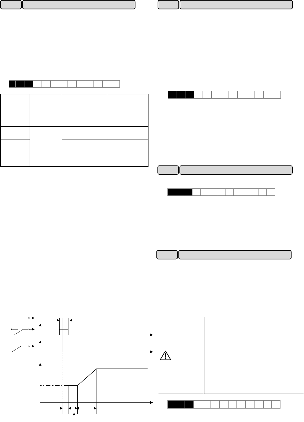
P24
STM
FWD
Time
0.1 s or
longer
0.2 s or
longer
ON
Time
Output
frequency
(motor speed)
Speed
search
In this section, the output
voltage is gradually increased
in steps to minimize shock.
Acceleration
ON
Note: The dotted-dashed line indicates motor speed.
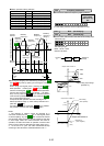
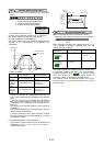
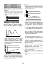
When the output frequency is fixed (constant-speed
operation) at light loads and except for”0.0” is set to F09,
"Torque boost 1," this function automatically reduces the
output voltage, while minimizing the product (power) of
voltage and current.
Auto tuning(P04/A13: 2) should be done to use this
function.
The energy-saving operation does not be operated when
set below.
- Under Torque control
- Selected the Automatic torque boost
- Selected the Torque vector control
- Under PG vector control
Set value 0: Inactive
1: Active
Note:
-Use this function for square law reduction torque loads
(e.g., fans, pumps). When used for a constant-torque
load or rapidly changing load, this function causes a delay
in control response.
-The energy-saving operation automatically stops
during acceleration and deceleration and when the
torque limiting function is activated.
This function selects the inverter stopping method when
a stop command is entered.
H 1 1 DEC M O D E
Set value 0: Deceleration-to-stop based on data set to
"H07 Non-linear acceleration and
deceleration"
1: Coasting-to-stop
Note:
This function is effective only when a stop command is
entered and, therefore, is ineffective when the motor is
stopped by lowering the set frequency.
An overcurrent trip generally occurs when current flows
above the inverter protective level following a rapid
change in motor load. The instantaneous overcurrent
limiting function controls inverter output and prohibits the
flow of a current exceeding the protective level even
when the load changes.
As the operation level of the instantaneous overcurrent
limiting function cannot be adjusted, the torque limiting
function must be used.
WARNING
As motor generation torque may be
reduced when instantaneous
overcurrent limiting is applied, set this
function to be inactive for equipment
such as elevators, which are
adversely affected by reduced motor
generation torque, in which case an
overcurrent trip occurs when the
current flow exceeds the inverter
protective level. A mechanical brake
should be used to ensure safety.
as accident may result.
H 1 2 INST C L
Set value 0: Inactive
1: Active
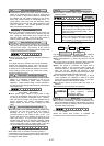
H 1 0 E N E R G Y S A V
H12 Instantaneous overcurrent limiting
H10 Energy-saving operation
H11 DEC mode
H09 Start mode