


5-33
Note1:
If REMOTE operation(F02: 1) is selected, operation signal is
given from terminal [FWD] or [REV].
Note2:
Use function "A13 Motor 2 (auto tuning)," to tune motor 2. In
this case, set values described in 1 and 2 above are for the
function (A01 - ) of motor 2.
WARNING
When the auto tuning value is set to 2,
the motor rotates at a maximum of half
the base frequency. Beware of motor
rotation.
as injury may result.
Long-time operation affects motor temperature and
motor speed. Online tuning minimizes speed changes
when motor temperature changes.
Auto tuning(P04/A13: 2) should be done to use this
function.
Set value Operation
0 Inactive
1 Active
This function sets the no-load current (exciting current)
of motor 1.
Setting range: 0.00 to 2,000A
Write this data when using a motor other than the FUJI
standard 3-phase motor and when the motor constant
and the impedance between the inverter and motor are
known.
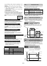
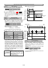
Calculate %R1 using the following formula:
()
100[%]×
・I3V/
R R1+Cable
%R1=
R1 : Primary coil resistance value of the motor [Ω]
Cable R : Output-side cable resistance value [Ω]
V : Rated voltage [V] I: Motor rated current [A]
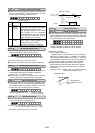
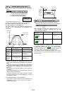
Calculate %X using the following formula:
()
()
100[%]×
・I3V/
X Cable+X2+XMX1+X2・XM/
%X =
X1 : Primary leakage reactance of the motor [Ω]
X2 : Secondary leakage reactance (converted to a
primary value)of the motor [Ω]
XM : Exciting reactance of the motor [Ω]
Cable X : Output-side cable reactance [Ω]
V : Rated voltage [V] I : Motor rated current[A]
Note:
For reactance, use a value in the data written in "F04
Base frequency 1."
When connecting a reactor or filter to the output circuit,
add its value. Use value 0 for cable values that can be
ignored.
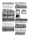
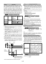
Changes in load torque affect motor slippage, thus causing
variations in motor speed. The slip compensation control
adds a frequency (proportional to motor torque) to the
inverter output frequency to minimize variations in motor
speed due to torque changes.
Auto tuning(P04/A13: 2) should be done to use this
function.
Set value: 0.00 to 15.00Hz
Calculate the amount of slip compensation using the
following formula:
[Hz]
n]speed[r/mi sSynchronou
/min]Slippage[r
×frequency =Base
amount ioncompenssat Slip
Slippage = Synchronous speed - Rated speed
P 0 9 SLIP C O M P 1
P 0 5 M 1 T U N 2
P 0 6 M 1 - I O
P 0 7 M 1 - % R 1
P 0 8 M 1 - % X
P06 Motor 1 (no-load current)
P05 Motor 1 (On-line Tuning)
P09 Slip compensation control
P08 Motor 1 (%X setting)
P07 Motor 1 (%R1 setting)