


5-35
This function selects the acceleration and deceleration
pattern.
Set value
0: Inactive (linear acceleration and deceleration)
1: S-shape acceleration and deceleration (mild)
2: S-shape acceleration and deceleration (*)
3: Curvilinear acceleration and deceleration
* The S-shape range is set by the
function: U02 to U05 when the set value "2" is selected.
The detail is referred to the function: U02 to U05.
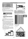
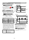
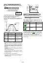
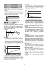
[S-shape acceleration and deceleration]
This pattern reduces shock by mitigating output frequency
changes at the beginning/end of acceleration and
deceleration.
Output frequency
0
f[Hz]
t[s]
βdec
βdec
βacc βacc
α
α
A
rbitrary S-shape
Mild S-shape ern
<Pattern constants>
When 1 is selected in H07
(mild S-shape pattern)
When 2 is selected in H07
(arbitrary S-shape pattern)
Range of
S-shape(
α
)
0.05 x max. output freq. (Hz)
(U02 to U05) x max. output
freq. (Hz)
Time for
S-shape at
acceleration
(
β
acc)
0.10 x acceleration time (s)
(U02, U03) x2 x
acceleration time (s)
Time for
S-shape at
deceleration
(
β
dec)
0.10 x deceleration time (s)
U04, U05 x2 x
deceleration time (s)
∗ When acceleration and deceleration times are very
long or short, acceleration and deceleration are rendered
linear.
It may be switched the acceleration and deceleration
time during constant speed or stopping by the function
"acceleration and deceleration time selection"(E01 to
E09: 4, 5).
The signal may be ignored switched during S-shape at
acceleration.
The linear deceleration time is corresponded if switched
during S-shape at deceleration.
It may be switched to the S-shape operation if output
frequency is reached to the setting frequency or change
to acceleration control.
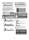
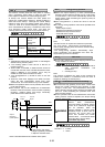
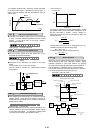
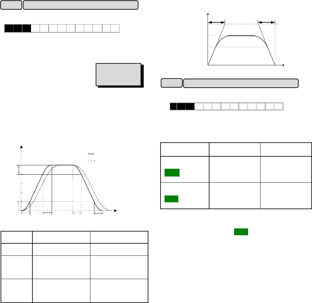
[ Curvilinear acceleration and deceleration ]
This function is used to minimize motor acceleration and
deceleration times in the range that includes a
constant-output range.
Deceleration time
Maximum
output
fre
q
uenc
y
Output
frequency
Base
frequency
t[sec]
0
A
cceleration time
Set
frequency
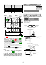
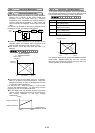
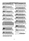
When accidental reversing is expected to cause a
malfunction, this function can be set to prevent reversal.
H 0 8 R E V L O C K
Set value 0: Inactive
1: Active
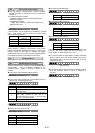
When reversible operation with polarity(set value: "4" or
"5") is selected in frequency command: F01, C30, the
inverter operates as follows.
Operation
command
0V to 10V input -10V to 0V input
Short FWD-CM
terminals or
: ON
The inverter operates. The frequency display
is "0.00" Hz.
Short REV-CM
terminals or
: ON
The frequency display
is "0.00" Hz.
The inverter operates.
This function prevents a reversing operation resulting from
a connection between the REV and P24 terminals,
inadvertent activation of the key, or negative analog
input from terminal 12 or V1. During this function is
operating, "0.00Hz" is displayed on the LED monitor.
This function cannot be prevented against H18: Torque
control function. It may be reverse because of the torque
signal and load.
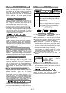
ACC/DEC (Mode select) pattern
H07
H 0 7 A C C P T N
Related functions
U02 to U05
H08
Rev. phase sequence lock
FWD
REV
REV