


3-1
3. Operation
3-1 Inspection and Preparation before Operation
Check the following before operation:
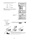
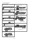
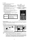
① Check that the connection is correct.
In particular, check that the power supply is not
connected to any of the U, V, and W output terminals and
that the ground terminal is securely grounded.
② Check for short-circuits and ground faults between the
terminals and live sections.
③ Check for loose terminals, connectors, or screws.
④ Check that the motor is separated from mechanical
equipment.
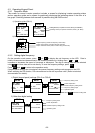
Fig. 3-1-1 Inverter connection
⑤ Turn off switches before turning power to ensure that the
inverter will not start or operate abnormally at power-on.
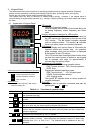
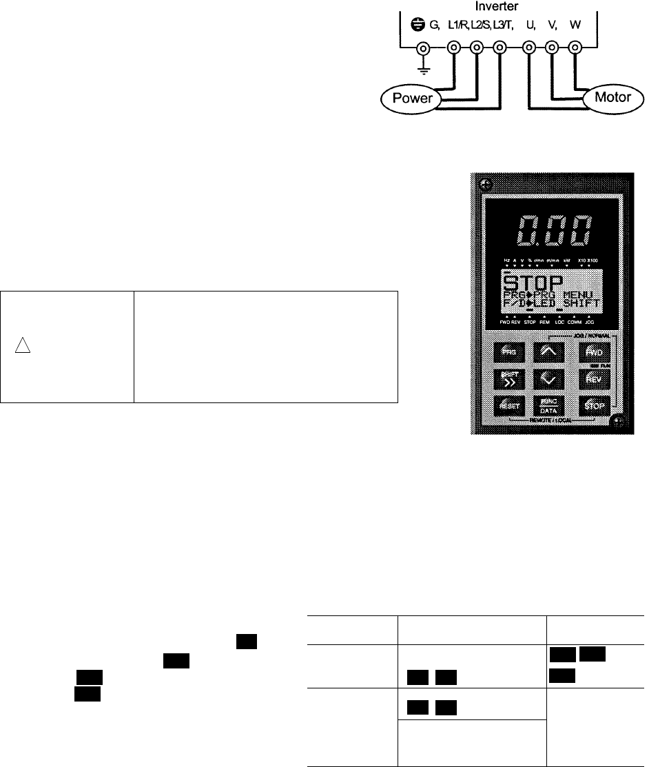
⑥ Check the following after power-on:
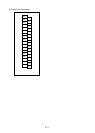
a. Check that no alarm message is displayed on the keypad
panel (see Figure 3-1-2).
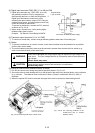
b. Check that the fan inside the inverter is rotating. (For
inverters with 2HP or more)
!
WARNING
Be sure to put on the surface cover
before turning on the power (close).
Never remove the cover while the power
is applied to the inverter.
To ensure safety, do not operate
switches with wet hands.
Electric shock may result
Fig. 3-1-2
Display on keypad panel at power-on
3-2 Operation Method
There are various methods of operation. Select a method of operation according to operating purpose and
specifications by referring to Section 4-2, "Operating the Keypad Panel," and Chapter 5, "Explanation of
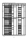
Functions." Table 3-2-1 lists general operation methods
3-3 Trial Run
Upon confirming that inspection results are normal (see Section 3-1), proceed with a trial run. The initial
operation mode (set at factory) is using the keypad panel.
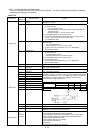
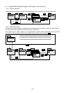
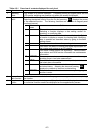
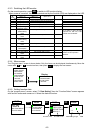
Table 3-2-1 General operation methods
Operation
command
Frequency setting
Operation
command
Operation
using keypad
panel
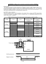
Keys on keypad panel
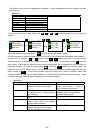
① Turn power on and confirm that frequency
display 0.00Hz is blinking on the LED monitor.
② Set the frequency to about 5Hz using key.
③ To start the run, press key (for forward
rotation) or key (for reverse rotation). To
stop, press key.
④ Check the following items :
a. Is the rotating direction correct?
b. Is the rotation smooth? (no buzzing or
abnormal vibration)
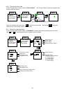
Operation
using
external
signal
terminals
Freq. Setting POT (VR),
analog voltage,
analog current
Contact input
(switch)
Terminals
FWD-CM and
REV-CM
c. Is acceleration and deceleration smooth?
If no abnormality is detected, increase the frequency and check the above items again.
If the results of the trial run are normal, start a formal run.
Notes: - If an error is detected in the inverter or motor, immediately stop the operation and attempt to
determine the cause of error referring to Chapter 7, "Troubleshooting."
- As voltage is still applied to the main circuit terminals (L1/R, L2/S, L3/T) and auxiliary
control-power terminals (R0, T0) even when the output from the inverter is terminated, do not
touch the terminals. The smoothing capacitor in the inverter is being charged after the power
is turned off and it is not discharged immediately. Before touching an electric circuit, confirm
that the charge lamp is off or a multimeter is indicating a low voltage at the terminals.
FWD
REV
STOP
∧
∧
∨
∧
∨
FWD
REV
STOP