


5-42
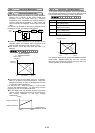
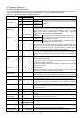
This function sets the maximum frequency for motor 2
output by the inverter. This function operates the same
as "F03 Maximum frequency 1." For details, see the
explanation for F03.
This function sets the maximum output frequency in the
constant-torque area of motor 2 (i.e., output frequency at
rated output voltage). This function operates the same
as "F04 Base frequency 1." For details, see the
explanation for F04.
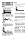
This function sets the rated value of voltage output to
motor 2. This function operates the same as "F05
Rated voltage 1." For details, see the explanation for
F05.
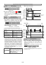
This function sets the maximum value of the inverter
output voltage of motor 2. This function operates the
same as "F06 Maximum voltage 1." For details, see the
explanation for F06.
A 0 4 M A X V - 2
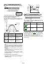
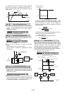
This function sets the torque boost function of motor 2.
This function operates the same as "F09 Torque boost
1." For details, see the explanation for F09.
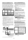
This function sets the function of the electronic thermal
overload relay for motor 2. This function operates the
same as F10 to F12, "Electronic thermal overload relay
1." For details, see the explanations for F10 to F12.
This function sets the torque vector function of motor 2.
This function operates the same as "F42 Torque vector
control 1." For details, see the explanation for F42.
This function sets the number of poles of motor 2 to be
driven. This function operates the same as "P01 Number
of motor-1 poles." For details, see the explanation for P01.
This function sets the capacity of motor 2. This function
operates the same as "P02 Motor 1 (Capacity)." For
details, see the explanation for P02. However, the
related motor data functions change to "A12 Motor 2
(Rated current)," "A15 Motor 2 (No-load current)," "A16
Motor 2 (%R1 setting)," and "A17 Motor 2 (%X setting)."
This function sets the rated current of motor 2. This
function operates the same as "P03 Motor 1 (Rated
current)." For details, see the explanation for P03.
This function sets the auto tuning of motor 2. This
function operates the same as "P04 Motor 1 (Tuning)."
For details, see the explanation for P04.
This function sets the online tuning of motor 2. This
function operates the same as "P05 Motor 1 (On-line
tuning)." For details, see the explanation for P05.
This function sets the no-load current of motor 2. This
function operates the same as "P06 Motor 1 (No-load
current)." For details, see the explanation for P06.
This function sets %R1 and %X of motor 2. This
function operates the same as "P07 Motor 1 (%R1
setting)," and "P08 Motor 1 (%X setting)." For details,
see the explanations for P07 and P08.
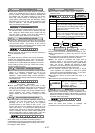
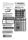
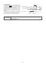
This function sets the amount of slip compensation for
motor 2. This function operates the same as "P09 Slip
compensation control." For details, see the explanation
for P09.
Set value : 0.00Hz to 15.00Hz
Calculate the amount of slip compensation using the
following formula:
Slip compenssation amount
][Hz
min]/r[ speed sSynchronou
min]/r[ Slippage
frequency Base ×=
Slippage = Synchronous speed-Rated speed
A 1 1 M2-CA P
A 0 5 T R Q B O O S T 2
A 0 9 T R Q V E C T O R 2
A 0 1 M A X H z - 2
A 1 2 M2- I r
A 0 2 B A S E H z - 2
A 1 3 M2 T U N 1
A 0 3 R A T E D V 2
A 1 4 M2 T U N 2
A 1 5 M2- I o
A 0 6 E L C T R N O L 2
A 0 7 O L L E V E L 2
A 0 8 T I M E C N S T 2
A 1 0 M 2 P O L E S
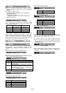
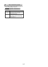
Motor 2 (A:Altemative Motor Parameters)
A01 Maximum frequency2
A02 Base frequency 2
A05 Torque boost 2
A03 Rated voltage 2
A11 Motor 2 (Capacity)
A12 Motor 2 (Rated current)
A06 Electronic thermal overload relay 2 (Select)
A07 Electronic thermal overload relay 2 (Level)
A08
Electronic thermal overload relay 2 (Thermal time constant)
A09 Torque vector control 2
A10 Number of motor-2 poles
A13 Motor 2 (Tuning)
A04 Maximum voltage 2
A14 Motor 2 (On-line tuning)
A15 Motor 2 (No-load current)
A16 Motor 2 (%R1 setting)
A17 Motor 2 (%X setting)
A18 Slip compensation control 2
A 1 6 M2 -%R 1
A 1 7 M2 -%X
A 1 8 SLI P C O M P 2