


5-15
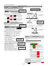
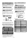
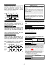
Holding time
Time
Forward rotation
Starting frequency
Stopping frequency
Output frequency
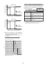
The starting frequency can be set to reserve the torque at
startup and can be sustained until the magnetic flux of the
motor is being established.
Frequency: This function sets the frequency at startup.
Setting range: 0.1 to 60Hz
Holding time: This function sets the holding time
during which the start frequency is sustained at startup.
Set values: 0.1 to 10.0 seconds
∗The holding time does not apply at the time of switching
between forward and reverse.
∗The holding time is not included in the acceleration time.
∗The holding time also applies when pattern operation
(C21) is selected. The holding time is included in the
timer value.
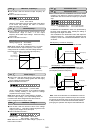
This function sets the frequency at stop.
Setting range: 0.0 to 60.0Hz
The operation does not start when the starting frequency
is less than the stopping frequency or when the setting
frequency is less than the stopping frequency.
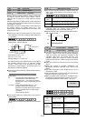
This function adjusts the carrier frequency, correct
adjustment of which prevents resonance with the
machine system, reduces motor and inverter noise, and
also reduces leakage current from output circuit wiring.
Nominal applied motor Setting range
75HP or less 0.75 to 15kHz
G11
100HP or more 0.75 to 10kHz
30HP or less 0.75 to 15kHz
40HP to 100HP 0.75 to 10kHz
P11
125HP or more 0.75 to 6kHz
Carrier frequency Low High
Motor noise High Low
Output current waveform
Bad Good
Leakage current
Small amount Large amount
Noise occurrence Extremely low High
The tone of motor noise can be altered when the carrier
frequency is 7kHz or lower. Use this function as
required.
Setting range: 0 , 1, 2 , 3
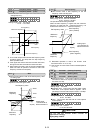
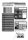
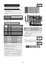
Monitor data (e.g.,output frequency, output current) can
be output to terminal FMA as a DC voltage. The amplitude
of the output can also be adjusted.
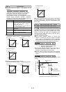
This function adjusts the voltage value of the monitor
item selected in F31 when the monitor amount is 100%.
A value from 0 to 200 (%) can be set in 1% steps.
Setting range: 0 to 200%
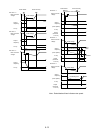
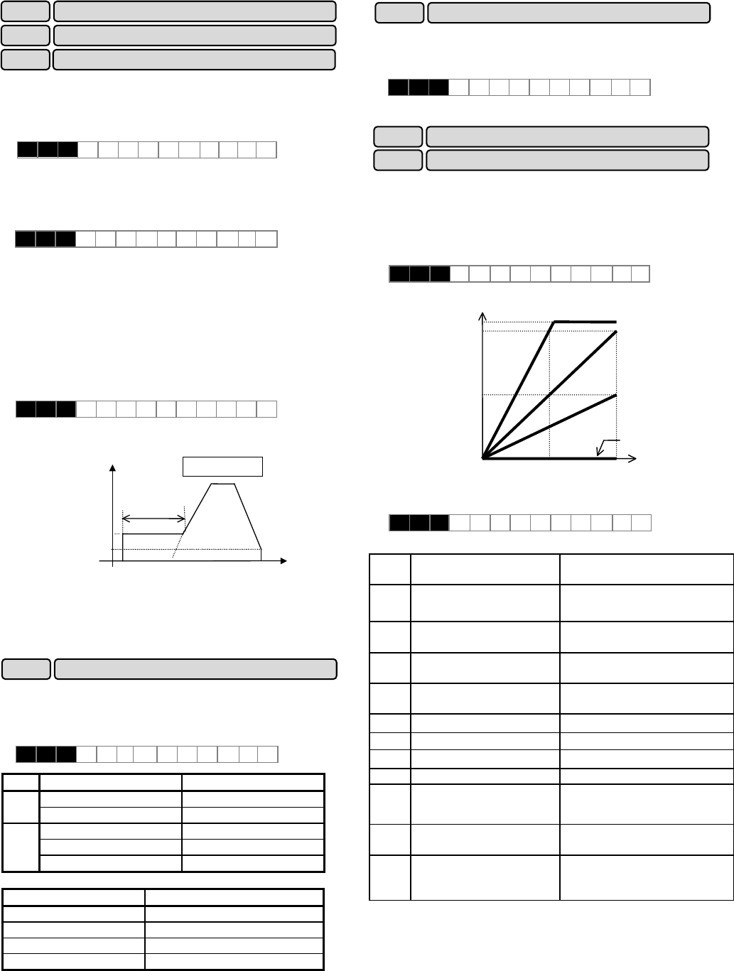
This function selects the monitor item to be output to
terminal FMA.
Set
value
Monitor item
Definition of 100% monitor amount
0 Output frequency 1
(before slip compensation)
Maximum output frequency
1 Output frequency 2
(after slip compensation)
Maximum output frequency
2 Output current Rated output current of
inverter x 2
3 Output voltage 230V series: 250V
460V series: 500V
4 Output torque Rated torque of motor x 2
5 Load rate Rated load of motor x 2
6 Power consumption Rated output of inverter x 2
7 PID feedback amount Feedback amount of 100%
8 PG feedback amount
(only when option is installed)
Synchronous speed at
maximum frequency
9 DC link circuit voltage 230V series: 500V
460V series: 1,000V
10 Universal AO
0 to 10V output through
communication and not related to
inverter operation.
※The power consumption shows "0" during regenerative load.
F30:200%
Higher than 10V
F30:0%
F30:50%
5V
10V
F30:100%
100%50%
FMA terminal output
voltage
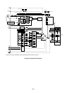
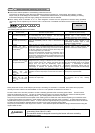
F23
F24
Starting frequency (frequency)
Start frequency (Holding time)
F25 Stop frequency
F30 FMA (voltage adjust)
FMA (function) F31
F26 Motor sound (carrier frequency)
F27 Motor sound (sound tone)
Notes:
1. Reducing the set value adversely affects the output
current waveform (i.e., higher harmonics), increases motor
loss, and raises motor temperature. For example, at
0.75kHz, reduce the motor torque by about15%.
2 Increasing the set value increases inverter loss and raises
inverter temperature.
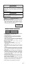
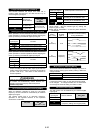
F 2 3 S T A R T H z
F 2 4 H O L D I N G t
F 2 5 S T O P H z
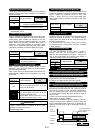
F 2 6 M T R S O U N D
F 2 7 MTR T O N E
F 3 0 FMA V - A D J
F 3 1 F M A F U N C