


Contents
1. Before Using This Product
・・・・・・・・・・・・・・・
1-1
1-1 Receiving Inspections
・・・・・・・・・・・・・・・・
1-1
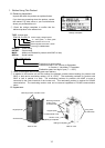
1-2 Appearance
・・・・・・・・・・・・・・・・・・・・・・・・
1-1
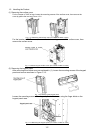
1-3 Handling the Product
・・・・・・・・・・・・・・・・・
1-2
1-4 Carrying
・・・・・・・・・・・・・・・・・・・・・・・・・・・・
1-3
1-5 Storage
・・・・・・・・・・・・・・・・・・・・・・・・・・・・
1-3
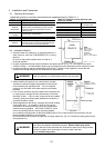
2. Installation and Connection
・・・・・・・・・・・・・・
2-1
2-1 Operating Environment
・・・・・・・・・・・・・・・
2-1
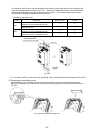
2-2 Installation Method
・・・・・・・・・・・・・・・・・・
2-1
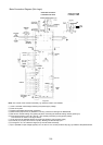
2-3 Connection
・・・・・・・・・・・・・・・・・・・・・・・・・
2-3
2-3-1 Basic connection
・・・・・・・・・・・・・・・・
2-3
2-3-2 Connecting the main circuit and
ground terminals
・・・・・・・・・・・・・・・・
2-8
2-3-3 Connecting the control terminals
・・・
2-13
2-3-4 Terminal arrangement
・・・・・・・・・・・・
2-16
2-3-5 Applicable equipment and wire size
for main circuit
・・・・・・・・・・・・・・・・・
2-18
3. Operation
・・・・・・・・・・・・・・・・・・・・・・・・・・・・・・
3-1
3-1 Inspection and Preparation
before Operation
・・・・・・・・・・・・・・・・・・・・・
3-1
3-2 Operation Method
・・・・・・・・・・・・・・・・・・・
3-1
3-3 Trial Run
・・・・・・・・・・・・・・・・・・・・・・・・・・・
3-1
4. Keypad Panel
・・・・・・・・・・・・・・・・・・・・・・・・・・
4-1
4-1 Appearance of Keypad Panel
・・・・・・・・・
4-1
4-2 Keypad Panel Operation System
(LCD screen, Level Structure)
・・・・・・・・
4-2
4-2-1 Normal operation
・・・・・・・・・・・・・・・・
4-2
4-2-2 Alarm occurrence
・・・・・・・・・・・・・・・・
4-2
4-3 Operating Keypad Panel
・・・・・・・・・・・・・
4-4
4-3-1 Operation Mode
・・・・・・・・・・・・・・・・・
4-4
4-3-2 Setting digital frequency
・・・・・・・・・・
4-4
4-3-3 Switching the LED monitor
・・・・・・・・
4-5
4-3-4 Menu screen
・・・・・・・・・・・・・・・・・・・・
4-5
4-3-5 Setting function data
・・・・・・・・・・・・・
4-5
4-3-6 Checking function data
・・・・・・・・・・・
4-7
4-3-7 Monitoring operating status
・・・・・・・
4-7
4-3-8 I/O check
・・・・・・・・・・・・・・・・・・・・・・・
4-8
4-3-9 Maintenance information
・・・・・・・・・・
4-9
4-3-10 Load rate measurement
・・・・・・・・
4-10
4-3-11 Alarm information
・・・・・・・・・・・・・・
4-11
4-3-12 Alarm history and factors
・・・・・・・・
4-12
4-3-13 Data copy
・・・・・・・・・・・・・・・・・・・・
4-13
4-3-14 Alarm mode
・・・・・・・・・・・・・・・・・・・
4-15
5. Function Select
・・・・・・・・・・・・・・・・・・・・・・・・
5-1
5-1 Function select list
・・・・・・・・・・・・・・・・・・・
5-1
5-2 Function Explanation
・・・・・・・・・・・・・・・・
5-7
6. Protective Operation
・・・・・・・・・・・・・・・・・・・・
6-1
6-1 List of Protective Operations
・・・・・・・・・・
6-1
6-2 Alarm Reset
・・・・・・・・・・・・・・・・・・・・・・・・
6-2
7. Trouble shooting
・・・・・・・・・・・・・・・・・・・・・・・
7-1
7-1 Protective function activation
・・・・・・・・・・
7-1
7-2 Abnormal motor rotation
・・・・・・・・・・・・・・
7-5
8. Maintenance and Inspection
・・・・・・・・・・・・・
8-1
8-1 Daily Inspection
・・・・・・・・・・・・・・・・・・・・・
8-1
8-2 Periodical Inspection
・・・・・・・・・・・・・・・・・
8-1
8-3 Measurement of Main Circuit
Electrical Quantity
・・・・・・・・・・・・・・・・・・・
8-4
8-4 Insulation Test
・・・・・・・・・・・・・・・・・・・・・・
8-5
8-5 Parts Replacement
・・・・・・・・・・・・・・・・・・
8-5
8-6 Inquiries about Products and
Product Guarantee
・・・・・・・・・・・・・・・・・・
8-5
9. Specifications
・・・・・・・・・・・・・・・・・・・・・・・・・・
9-1
9-1 Standard Specifications
・・・・・・・・・・・・・・
9-1
9-2 Common Specifications
・・・・・・・・・・・・・・
9-3
9-3 Outline Dimensions
・・・・・・・・・・・・・・・・・・
9-4
9-4 RS-485 Modbus RTU Serial
Communications
・・・・・・・・・・・・・・・・・・・・
9-8
9-4-1 Transmission Specification
・・・・・・・・
9-8
9-4-2 Connection
・・・・・・・・・・・・・・・・・・・・・・
9-8
9-4-3 Serial Interface Configuration
・・・・・・
9-8
9-4-4 Modbus RTU Functions
・・・・・・・・・・・
9-8
9-4-5 Inverter Function Code Access
・・・・・
9-9
9-4-6 Command and Monitor
Data Registers
・・・・・・・・・・・・・・・・・・
9-9
9-4-7 Data Format Specification
・・・・・・・・
9-11
9-4-8 Communication Errors
・・・・・・・・・・・
9-15
10. Options
・・・・・・・・・・・・・・・・・・・・・・・・・・・・・
10-1
10-1 Built-in Options
・・・・・・・・・・・・・・・・・・・
10-1
10-2 Separately Installed Options
・・・・・・・・
10-2
11. Electromagnetic compatibility (EMC)
・・・・
11-1
11-1 General
・・・・・・・・・・・・・・・・・・・・・・・・・・
11-1
11-2 Recommended Installation
Instructions
・・・・・・・・・・・・・・・・・・・・・・
11-2
11-3 The harmonics restriction
in Europe Union (EU)
・・・・・・・・・・・・・
11-5