


5-40
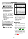
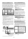
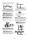
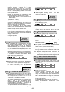
-To suppress vibration with a frequency roughly equivalent
to the value "H24 D-gain," decrease the value of H24. If
there is residual vibration with 0.0, decrease the value of
"H22 P-gain."
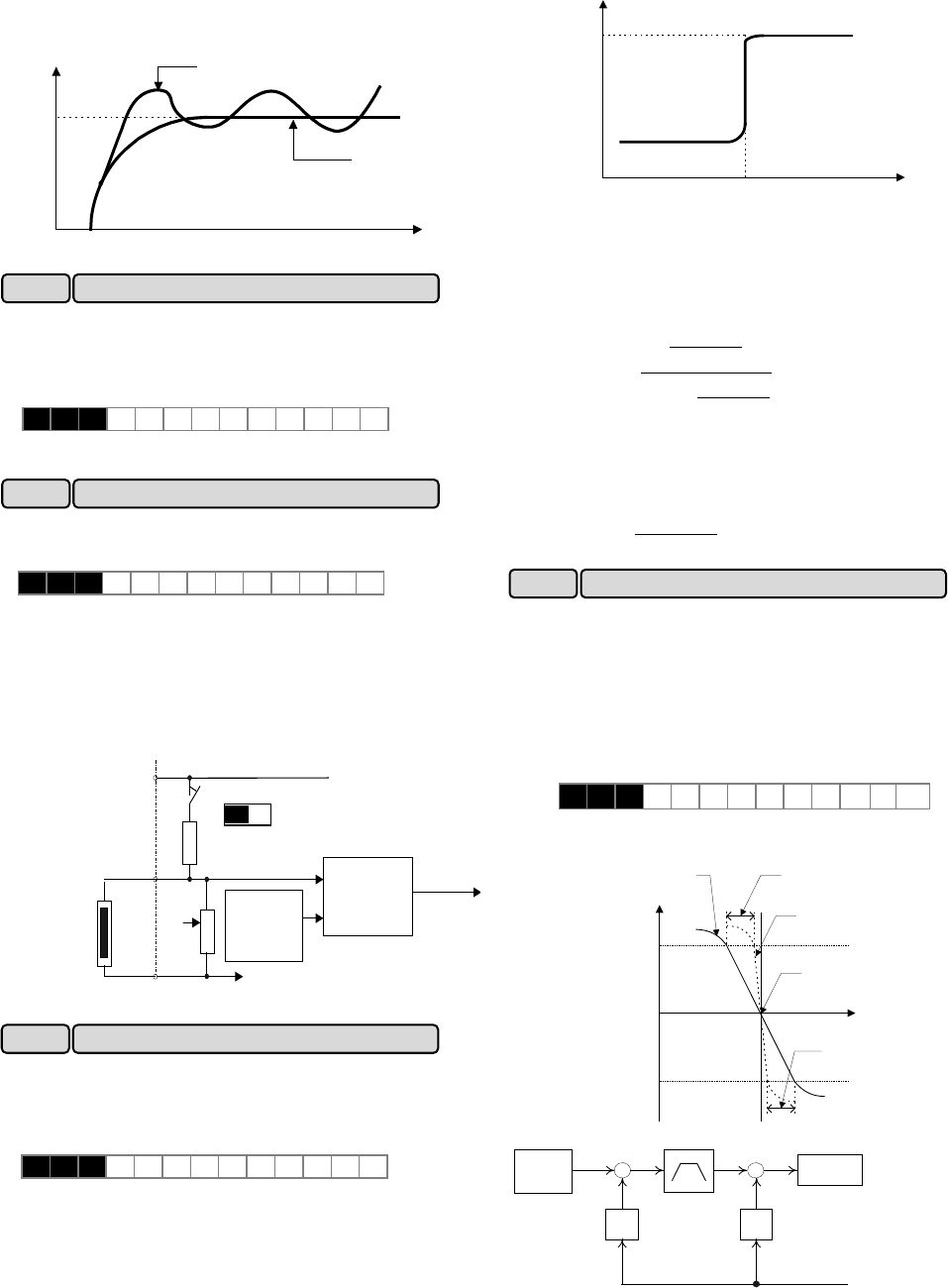
Response
Before
adjustment
After
adjustment
Time
This filter is for feedback signal input from terminal [12]
or [C1]. This filter stabilizes operation of the PID control
system. A set value that is too large, however,
deteriorates response.
H 2 5 F B F I L T E R
Setting range: 0.0 to 60.0 seconds
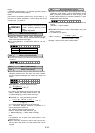
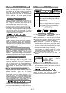
Set this function active when the motor has a PTC
thermistor for overheat protection
Set value 0: Inactive
1: Active
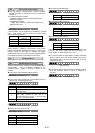
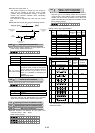
Connect the PTC thermistor as shown in the figure
below.
Turn on switch “PTC” on the control PCB.
The trip mode is activated by “OH2:External thermal
relay tripped.”
PTC
thermistor
H27
(Level)
Comparator
OH2
DC10V
Resistor
250 Ohom
0V
13
C1
11
ON OFF
PTC
1k Ohom
The voltage input to terminal [C1] is compared to the set
voltage (Level). When the input voltage is equal to or
greater than the set voltage (Level), "H26 PTC thermistor
(Mode select)," starts.
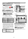
Setting range: 0.00 to 5.00V
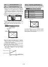
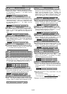
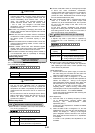
The PTC thermistor has its own alarm temperature. The
internal resistance value of the thermistor largely change
at the alarm temperature. The operation (voltage) level
is set using this change in the resistance value.
Internal resistance of
PTC thermistor
Rp2
Rp1
Temperature
Alarm
temperature
The figure in "H26 PTC thermistor (Mode select)," shows
that resistor 250Ω and the thermistor (resistance value
Rp) are connected in parallel. Hence, voltage Vc
1
(Level) at terminal [C1] can be calculated by using the
following formula.
][
・
・
V10
Rp250
Rp250
1000
Rp250
Rp250
Vc
1
×
+
+
+
=
The operation level can be set by bringing Rp in the Vc
1
calculation formula into the following range.
Rp
1
< Rp < Rp
2
To obtain Rp easily, use the following formula.
[Ω]
2
RpRp
Rp
21
+
=
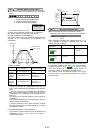
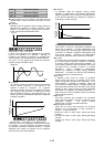
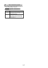
When two or more motors drive a single machine, a higher
load is placed on the motor rotating the fastest. Droop
operation achieves a good load balance by applying
drooping characteristics to speed against load variations.
Auto tuning(P04: 2) should be done to use this function.
This function cannot be used when the motor 2 is selected.
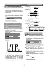
The drooping speed at constant torque is set.
Set value
: -9.9Hz to 0.0Hz
Rated torque
(drive)
0 Speed
Torque
When droop operation
is active
When droop operation
is inactive
Characteristics of the motor
Rated torque
(brake)
Freq. setting
Setting value of |H28|
Setting value of |H28|
Output
freq.
+
Feedback amount
Freq.
setting
value
+
H28
Droop freq.
Acc/Dec calculation
+
P09
Slip compensation freq.
+
τ
Torque calculation
+ : drive
- : brake
H 2 6 P T C M O D E
H 2 8 DROO P
H28 Droop operation
H26 PTC thermistor (Mode select)
H27 PTC thermistor (Level)
H 2 7 P T C L E V E L
H25 PID control (Feedback filter)