


5-24
This function outputs an inverted signal to Running
(RUN) to indicate zero speed. An ON signal is output
when the DC injection brake function is operating.
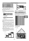
This function outputs an ON signal when the inverter is
ready to operate. The inverter is ready to operate when
the main circuit and control circuit power is established
and the inverter protective function is not activating.
About one second is required from power-on to ready for
operation in normal condition.
To perform switching operation between the line and the
inverter, the sequence prepared in the inverter can be
used to select and output signals for opening and closing
the magnetic contactors connected to the inverter. As
the operation is complex, refer to technical
documentation for the FRENIC5000G11S series when
using this function.
As the sequence will operate automatically when SW88
or SW52-2 is selected, do not select when not using the
sequence.
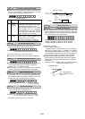
When a signal for switching to motor 2 is input from the
terminal selected by terminals [X1] to [X9], this function
selects and outputs the signal for switching the magnetic
contactor for the motor. As this switching signal is not
output during running including when the DC injection
braking function is operating, a signal must be re-input
after output stops.
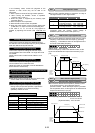
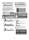
When an operation (forward or reverse) command is
entered, this function outputs an ON signal. When a
stop command is entered, the signal goes off after
inverter output stops. When a coast-to-stop command
is entered and the inverter protective function operates,
the signal goes off immediately.
When the pattern operation stage changes, this function
outputs a one-shot (100ms) ON signal to report a stage
change.
When the seven stages of a pattern operation are
completed, this function outputs a one-shot (100 ms) ON
signal to report the completion of all stages.
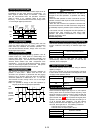
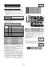
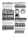
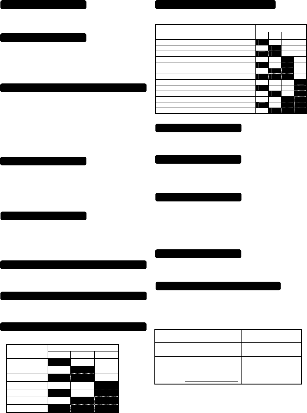
During pattern operation, this function reports the stage
(operation process) being operated.
Output terminal
Pattern operation
stage No.
STG1 STG2 STG4
Stage 1
on off off
Stage 2
off on off
Stage 3
on on off
Stage 4
off off on
Stage 5
on off on
Stage 6
off on on
Stage 7
on on on
When pattern operation is not activated (i.e., no stage is
selected), the terminals do not output a signal.
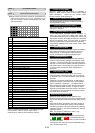
This function reports the operating status of the inverter
protective function.
Output terminal
Alarm detail
(inverter protective function)
AL1 AL2 AL4 AL8
Overcurrent, ground fault, fuse blown
on off off off
Overvoltage
off on off off
Undervoltage shortage, input phase failure
on on off off
Motors 1 and 2 overload
off off on off
Inverter overload
on off on off
Heat sink overheating, inverter inside overheating
off on on off
External alarm input, braking resistor overheating
on on on off
Memory error, CPU error
off off off on
Keypad panel communication error, option communication error
on off off on
Option error
off on off on
Output wiring error
off off on on
RS-485 communication error
on off on on
Overspeed, PG disconnection
off on on on
In normal operation terminals do not output a signal.
When used with "H06 Cooling fan ON/OFF control," this
function outputs a signal while the cooling fan is
operating.
When a value of 1 or larger is set to "H04 Retry
operating," the signal is output while retry operation is
activating when the inverter protective function is
activated.
Assigning value "27" to a transistor output terminal
renders the terminal a universal DO terminal.
This function enables ON/OFF through the RS-485 and
BUS option.
This function serves only to turn on and off the transistor
output through communication and is not related to
inverter operation.
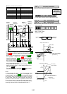
This function outputs a early warning signal when heat
sink temperature is (overheat detection level - 10℃) or
higher.
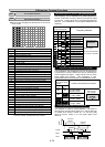
When either of data for the Life expectancy judgment
of the function code:U09 to U11 reaches at the Life
expectancy judgment level, the ON signal is output.
However, the inverter does not do alarm.
Moreover, the alarm output for any fault (30A, 30B,
30C ) does not operate.
Function
code
Parts of
Life expectancy judgment
Life expectancy
judgment level
U09
Capacitor in main circuit 85% or less of the initial value
U10
Electrolytic capacitor on PCB 61,000 hours
U11
Cooling fan 25,000 hours
U59
DC fan broken for stir internal
unit up
[40HP or more is corresponded.]
DC fan is broken
Inverter stopping [STOP]
Ready output [RDY]
Line/Inv changeover [SW88] [SW52-2] [SW52-1]
Auto-resetting [TRY]
Cycle completion signal for pattern operation [TO]
Motor 2 /Motor 1 [SWM2]
Auxiliary terminal [AX]
Time-up signal for pattern operation [TU]
Stage No. indication for pattern operation [STG1] [STG2] [STG4]
Alarm indication [AL1] [AL2] [AL4] [AL8]
Overheat early warning [OH]
Fan operation signal [FAN]
Universal DO [U-DO]
Life expectancy detection signal [LIFE]