


5-26
Select one of the following two types of overload early
warning: early warning by electronic thermal O/L relay
function or early warning by output current.
Set value 0: Electronic thermal O/L relay
1: Output current
Set
value
Function Description
0
Electronic
thermal
O/L relay
Overload early warning by electronic
thermal O/L relay (having inverse-time
characteristics) to output current.
The operation selection and thermal
time constant for the inverse-time
characteristics are the same as those
of the electronic thermal O/L relay for
motor protection (F10 and F12).
1
Output
current
An overload early warning is issued
when output current exceeds the set
current value for the set time.
The figure of OL2(E37) is refferred.
This function cannot be used when Motor 2 is selected.
This function determines the operation level of the
electronic thermal O/L relay or output current.
Setting range G11S:Inverter rated output current x (5 to 200%)
P11S:Inverter rated output current x (5 to 150%)
The operation release level is 90% of the set value.
This function cannot be used when Motor 2 is selected.
This function is used when 1 (output current) is set to
"E33 Overload early warning (operation selection)."
Setting range: 0.1 to 60.0 seconds
Set the time from when the operation level is attained
until the overload early warning function is activated.
This function determines the operation (detection) level
of output frequency for “2nd Freq. level detection [FDT2]”.
The hysteresis width for operation release is set by the
function E32: FDT1 function signal (Hysteresis).
Setting range(Operation level) : G11S: 0 to 400 Hz
P11S: 0 to 120 Hz
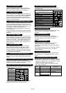
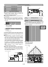
This function determines the operation level of the output
current for “2nd OL level detection [OL2]”.
Setting range G11S:Inverter rated output current x (5 to 200%)
P11S:Inverter rated output current x (5 to 150%)
The operation release level is 90% of the set value.
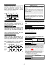
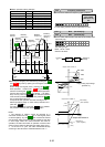
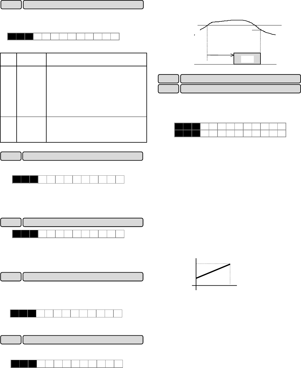
ON
E37 OL2 LEVEL
E35
OL TIMER
[OL2]
Output current
OL2 LEVEL x 90%
(E34 OL1 LEVEL)
(OL1 LEVEL x 90%)
These coefficients are conversion coefficients which are
used to determine the load and line speed and the target
value and feedback amount (process amount) of the PID
controller displayed on the LED monitor.
Setting range
Display coefficient A:-999.00 to 0.00 to +999.00
Display coefficient B:-999.00 to 0.00 to +999.00
Load and line speed
Use the display coefficient A.
Displayed value = output frequency x (0.01 to 200.00)
Although the setting range is ±999.00, the effective
value range of display data is 0.01 to 200.00. Therefore,
values smaller or larger than this range are limited to a
minimum value of 0.01 or a maximum value of 200.00.
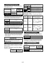
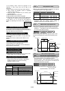
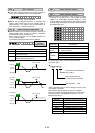
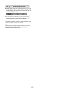
Target value and feedback amount of PID controller
Set the maximum value of display data in E40, "Display
coefficient A," and the minimum value in E41, "Display
coefficient B."
Displayed value = (target value or feedback amount)
x (display coefficient A - B)+B
E 3 3 O L W A R N I N G
E 3 4 O L 1 L E V E L
E 3 5 O L 1 T I M E R
E 4 0 COEF A
E 4 1 COEF B
E34 OL function signal (Level)
E35 OL function signal (Timer)
Displayed value
A
Target value or
feedback amount
B
0%
100%
E33 OL function signal (mode select)
E36 FDT2 function (Level)
E 3 6 F D T 2 L E V E L
E37 OL2 function (Level)
E 3 7 O L 2 L E V E L
E40 Display coefficient A
E41 Display coefficient B