9
CHAPTER 2 MEMORY ARCHITECTURE
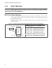
■ Contents of Vector Table Areas
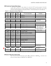
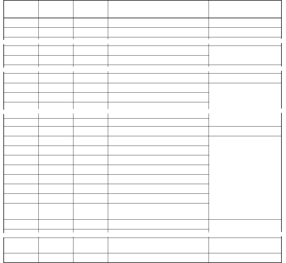
A vector table is composed of entry addresses for each of the "EIT" processing programs. Each table
contains some values whose use is fixed according to the CPU architecture, and some that vary according
to the types of built-in peripheral circuits present. Table 2.1-1 shows the structure of a vector table area.
*: Even when the "TBR" value is changed, the reset vector remains the fixed address "000FFFFC
H
".
■ Vector Table Area Initial Value
After a reset, the value of the table base register (TBR) is initialized to "000FFC00
H
", so that the vector
table area is between addresses "000FFC00
H
" and "000FFFFF
H
".
Table 2.1-1 Structure of a Vector Table Area
Offset from
TBR
Number
(hex)
Model-
dependent
EIT value description Remarks
000
H
FF
H
No
INT #0FF
H
004
H
FE
H
No
INT #0FE
H
2F8
H
41
H
No System reserved
Do not use
2FC
H
40
H
No System reserved
33C
H
30
H
No
INT #030
H
340
H
2F
H
Ye s
INT #02F
H
or IR31
Values will increase
towards higher limits
when using over 32-
source extension.
Refer to User’s Manual
for each model.
344
H
2E
H
Ye s
INT #02E
H
or IR30
3BC
H
10
H
Yes INT #010
H
or IR00
3C0
H
0F
H
No
INT #00F
H
or NMI
3C4
H
0E
H
No Undefined instruction exception
3C8
H
0D
H
No Emulator exception
3CC
H
0C
H
No Step trace break trap
3D0
H
0B
H
No Operand break trap
3D4
H
0A
H
No Instruction break trap
3D8
H
09
H
No Emulator exception
3DC
H
08
H
No
INT #008
H
or coprocessor error trap
3E0
H
07
H
No
INT #007
H
or coprocessor not-found
trap
3E4
H
06
H
No System reserved
Do not use
3F8
H
01
H
Yes System reserved or Mode Vector
Refer to User’s Manual for
each model.
3FC
H
00
H
No Reset *
⎨
⎧
⎩
~
~ ~ ~ ~
~
⎨
⎪
⎧
⎩
⎪
~
~ ~ ~ ~
~
⎨
⎧
⎩
~
~ ~ ~ ~
~
~
~ ~ ~ ~
~


