


35
CHAPTER 4 RESET AND "EIT" PROCESSING
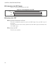
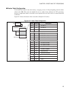
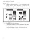
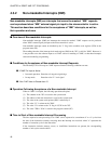
■ Vector Table Configuration
Vector tables are located in the main memory, occupying an area of 1 Kbyte beginning with the address
shown in the TBR. These areas are intended for use as a table of entry addresses for "EIT" processing,
however in applications where vector tables are not required, this area can be used as a normal instruction
or data area.
Figure 4.2-2 shows the structure of the vector table. (Example of 32-source)
Figure 4.2-2 Vector Table Configuration
TBR
00000000
H
FFFFFFFFH
1 Kbyte
Memory space
Offset Vector no. Description
000
H
004H
008H
33CH
340H
344H
3BCH
3C0H
3C4H
3C8H
3CCH
3D0H
3F8H
3FCH
FFH
FEH
FDH
30H
2FH
2EH
10H
0FH
0EH
0DH
0CH
0BH
01H
00H
INT #0FFH
INT #0FEH
INT #0FDH
INT #030H
INT #02FH or IR31
INT #02E
H or IR30
INT #010
H or IR00
INT #00F
H or NMI
Undefined instruction exception
Emulator exception
Step trace trap
Operand break trap
System reserved or Mode Vector
Reset