20
CHAPTER 3 REGISTER DESCRIPTIONS
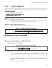
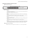
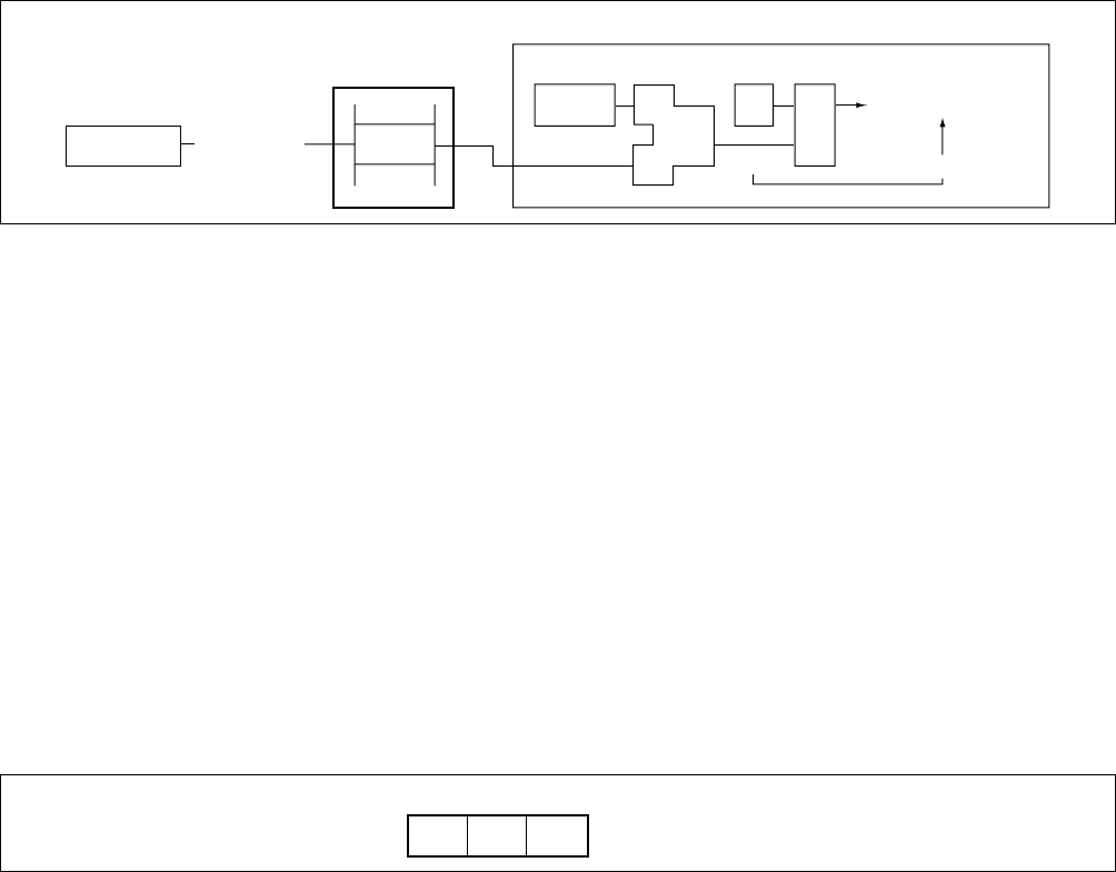
Figure 3.3-4 "ILM" Register Functions
● Range of ILM Program Setting Values
If the original value of the register is in the range 16 to 31, the new value may be set in the range 16 to 31.
If an instruction attempts to set a value between 0 and 15, that value will be converted to "setting value +
16" and then transferred.
If the original value is in the range 0 to 15, any new value from 0 to 31 may be set.
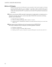
● Initialization of the ILM at Reset
The reset value is "01111
B
".
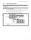
■ System Condition Code Register (SCR: Bit 10 to bit 08)
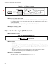
● Bit Configuration of the SCR
Figure 3.3-5 Bit Configuration of the SCR
● SCR Functions
• Bits D1, D0
Bits "D1", "D0" are used for intermediate data in stepwise division calculations. This register is used to
assure resumption of division calculations when the stepwise division program is interrupted during
processing. If changes are made to the contents of this register during division processing, the results of
the division are not assured.
•T-bit
The T-bit is a step trace trap flag. When this bit is set to "1", step trace trap operation is enabled.
Note: Step trace trap processing routines cannot be debugged using emulators.
● Initialization of the SCR at Reset
The values of bits "D1", "D0" are undefined, and the T-bit is set to "0".
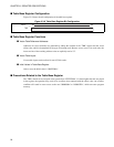
Interrupt controller
Interrupt activated
Peripheral
Interrupt
request
Activation OK
ICR
25
ILM
29
Comp
29>25
1
I flag
FR family CPU
AND
10 09 08
SCR D1 D0 T Initial value: XX0
B


