


This soft copy for use by IBM employees only.
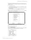
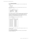
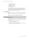
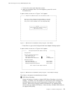
┌──────────────────────────────────────┐
│ PCI Bus Control │
├──────────────────────────────────────┤
│ PCI Data Parity NMI [Enabled ] │
│ CPU-PCI Write Buffers [Disabled] │
│ SCSI ROM Address [C8000 ] │
│ PCI Primary Bus MLT [30h] │
│ PCI Secondary Bus MLT [90h] │
│ • PCI Interrupt Requests │
└──────────────────────────────────────┘
PCI Data Parity NMI enables the generation of a non-maskable interrupt when a
PCI data parity error occurs. CPU-PCI Write Buffers enables the CPU to PCI
write posting. SCSI ROM Address lets you specify the I/O address of the
server′s imbedded SCSI controller. The PCI Master Latency Timer values can
be set for both the primary and secondary buses.
2.1.2 BIOS Updates
The BIOS of PCI/EISA servers are located in a flash ROM on the motherboard. If
necessary, it can be updated with a new version that can be obtained from the
Web.
For more information on how to obtain BIOS updates, please refer to
Appendix A, “Sources of Drivers and Information” on page 147.
2.2 EISA Configuration Utility
This utility is used when you add or remove an ISA or EISA adapter. We use an
example to illustrate the process. In our example, we add an Auto Token-Ring
16/4 ISA adapter in slot 3 of a PC Server 320. The steps to complete the process
are as follows:
1. Boot with the EISA configuration utility diskette.
2. Answer Y to the following question:
Do you want to configure your system now [Y,N]?
3. The welcome panel will appear. Press Enter to continue. A panel similar to
the one in Figure 3 on page 10 will then appear.
Chapter 2. Hardware Configuration 9