


NDA-24296 CHAPTER 2
Page 79
Revision 1.0
PH-IO24
Input/Output Controller
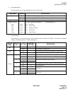
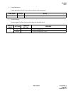
4. Lamp Indications
The table below shows lamp indications on this circuit card.
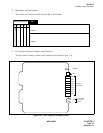
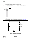
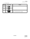
5. Switch Settings
The following is a brief description of the switches on this circuit card. When a switch has a standard
setting, it is indicated with “×” in the table below.
LAMP NAME COLOR DESCRIPTION
OPE/MB Green This circuit card is operating normally.
Red This circuit card is placed in the Make-busy state.
IOC ALM Red Clock down WDT alarm occurs to the microprocessor.
PORT0 - PORT3 RS-232C signal status indication. n = port number (0-3)
SDn Green SD: Send Data
RDn Green RD: Receive Data
ERn Green ER: Equipment Ready
DRn Green DR: Data Ready
CDn Green CD: Carrier Detect
SWITCH
NAME
SWITCH
NO.
SETTING
STANDARD
SETTING
DESCRIPTION
MB
Up The circuit card is placed into Make-busy status.
Down × Cancellation of Make-busy.
MBR
Up The circuit card is placed into Make-busy request status.
Down × Cancellation of Make-busy Request.
SW50
1
ON This circuit card is used as the extended I/O circuit card #1.
OFF This circuit card is used as the extended I/O circuit card #0.
2
ON
Not used (For Business System Only).
OFF
×
2
ON Free Wheeling with ACK signal (For Hotel System Only).
OFF
×
Free Wheeling.
3
ON
Not used.
OFF ×
4
ON
Not used.
OFF ×