


CHAPTER 3 NDA-24296
Page 202
Revision 1.0
PH-CK16-A
Phase Lock Oscillator
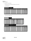
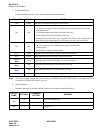
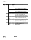
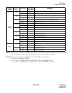
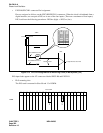
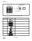
• EXCLK0/EXCLK1 connector Pin Assignment
Pins are assigned as follows on the EXCLK0/EXCLK1 connectors. When the clock is distributed from a
digital interface, use one pair of DIUxxx in one of the four inputs. (There are a maximum of four inputs.)
DIU leads have the following precedence: DIU0xx (high) → DIU3xx (low).
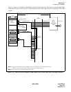
Figure 3-13 PLO Pin Assignments for Receiving Clock (4 IMG System) (2/2)
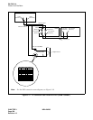
PLO input leads appear on the LT connectors labeled EXCLK0 and EXCLK1.
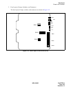
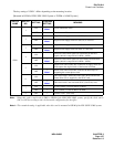
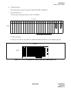
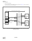
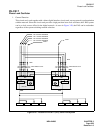
• PLO mounting slots
The PLO card is mounted in Slots 09 and 13 of ISWM.
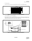
34PH ISWM EXCLK CA-A
34PH ISWM EXCLK CA-A
REAR VIEW
EXCLK0
EXCLK1
TSWM
MDF
Installation Cable To Digital Interface and/or DCS
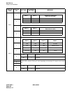
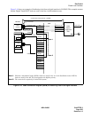
34PH ISWM EXCLK CA-A Cable Lead Location
26
27
28
29
30
31
32
33
34
35
36
37
38
1
2
3
4
5
6
7
8
9
10
11
12
13
FM1
FM0
DIU3B
DIU2B
DIU1B
DIU0B
DCSB
SYN1B
SYN0B
E
E
DIU3A
DIU2A
DIU1A
DIU0A
DCSA
SYN1A
SYN0A
00 01 02 03 04 05 06 07 08 09 10 11 12 13 14 15 16 17 18 19 23
EXCLK0
EXCLK1
PLO
PLO
Front View
ISWM