


CHAPTER 3 NDA-24296
Page 596
Revision 1.0
PA-24DTR (DTI)
Digital Trunk Interface
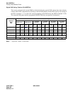
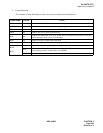
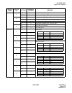
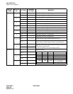
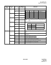
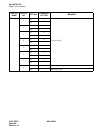
5. Switch Settings
Standard settings of switches on this circuit card are shown in the table below.
Note:
This switch setting is applicable for a system adopts Associated Channel Interoffice Signalling (ACIS).
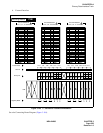
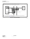
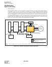
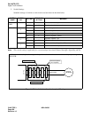
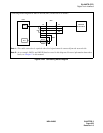
Figure 3-187 Available Locations for Loopback Testing
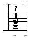
SWITCH
NAME
SWITCH
NO.
SETTING
STANDARD
SETTING
MEANING
SW00
(MB)
UP Circuit card make busy
DOWN ¥ Circuit card make busy cancel
SW01/13B
0
ON Internal Loopback : Set
OFF ¥ Internal Loopback : Cancel
1
ON External Loopback : Set
OFF ¥ External Loopback : Cancel
2
ON Payload Loopback : Set
OFF ¥ Payload Loopback : Cancel
3
ON All Channel Make Busy : Set Note
OFF ¥ All Channel Make Busy : Cancel
Switch
TDSW Interface
PAD
Speech Path
Control Block
Framer
Line Interface
DIGITAL
NETWORK
External Loopback
(Line Loopback)
Payload Loopback
Internal Loopback
R
T
Speech Path
PA-24 DTR (DTI)
As illustrated below, loopback testing can be performed at three locations on this card by key setting of the
SW01/13B.