


CHAPTER 2 NDA-24296
Page 80
Revision 1.0
PH-IO24
Input/Output Controller
6. External Interface
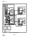
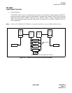
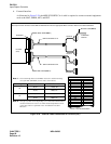
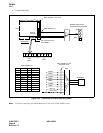
As illustrated in Figure 2-29, the 68PH S 2PORTS CA-A cable is required to connect external equipment
such as the MAT, SMDR, MCI, and PRT.
Figure 2-29 External Cable Connection for PH-IO24 (IOC)
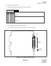
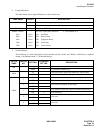
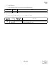
Securely insert the connector of the 68PH S 2PORTS CA-A into the appropriate MISC connector. Refer to the table listed below.
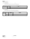
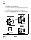
The relationship between the MISC connectors and the mounting
slot of the IOC (PH-IO24) circuit card is shown below.
The type of cables varies depending on a connected terminal and/or
whether modems are used or not. More detailed information on the
connecting cables is explained in the “Installation Procedure
Manual”.
MISC 3B/2B (Note 1)
68PH S 2PORTS CA-A
Backplane
PH-IO24
(IOC)
Circuit #0
Circuit #1
Circuit #2
Circuit #3
RS-232C cable (Note 2)
68PH S 2PORTS CA-A
MISC 3A/2A (Note 1)
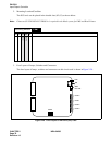
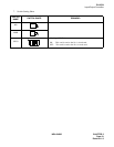
17
16
15
14
13
12
11
ST2
10
ST1
09
RT
08
PB/CI
07
ER
06
CD
05
SG
04 CS
03 RS
02 RD
01 SD
Pin Signal name
42
41
40
39
38
37
36
35
34
33
32
31
30
29
28
27
26
Pin Signal name
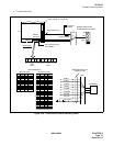
TYP0, 1 Connector
AMP AMP
TYP0 TYP1
TYP1TYP0
To RS-232C
Terminal
DR
TYP0, 1 Lead Accommodation
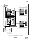
Note 1:
Note 2:
Mounting Slot
02
03
IOC Circuit Number
#0, #1
#2, #3
#0, #1
#2, #3
MISC 2B
MISC 2A
MISC 3B
MISC 3A
MISC Connector