


CHAPTER 3 NDA-24296
Page 264
Revision 1.0
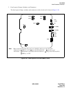
PA-CS02-C
Attendant Interface
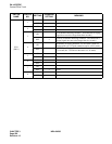
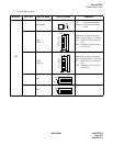
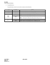
4. Lamp Indications
The contents of lamp indications on this circuit card are shown in the table below.
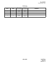
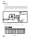
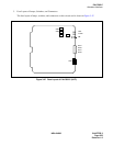
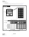
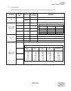
5. Switch Settings
Standard settings of switches on this circuit card are shown in the table below.
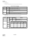
Table 3-2 ATI Card Lamp Indication
LAMP COLOR STATE
OPE Green Remains lit while this circuit card is operating.
N-OPE Red Remains lit while this circuit card is in make-busy state.
BLS0
BLS1
Red Lights when the corresponding sender circuit is in use.
Flash
Flashes when the corresponding sender circuit is in make-busy state or when select signals
are being transmitted.
BLA0
BLA1
Red Lights when the corresponding circuit is busy.
Flash Flashes when the corresponding circuit is in make-busy state.
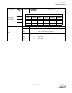
SWITCH
SWITCH
NO.
SETTING
STANDARD
SETTING
MEANING
MB
—
UP Circuit card make busy
DOWN
×
Circuit card make busy cancel
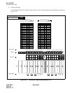
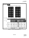
SW2 (TAS1)
SW3 (TAS0)
1
2
3
4
SETTING OF TAS CURRENT LIMIT RESISTANCE
SW2-1/
SW3-1
SW2-2/
SW3-2
SW2-3/
SW3-3
SW2-4/
SW3-4
RESISTANCE
ON
OFF
ON
OFF
ON
OFF
ON
OFF
ON
ON
OFF
OFF
ON
ON
OFF
OFF
ON
ON
ON
ON
OFF
OFF
OFF
OFF
OFF
OFF
OFF
OFF
OFF
OFF
OFF
OFF
0
Ω
200
Ω
390
Ω
590
Ω
820
Ω
1020
Ω
1210
Ω
1410
Ω