


CHAPTER 2 NDA-24296
Page 106
Revision 1.0
PH-PC45
Emergency Alarm Controller
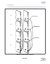
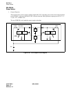
2. Mounting Location/Condition
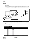
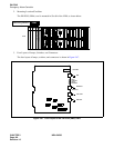
The PH-PC45 (EMA) card is mounted in Slot 04 of the LPM, as shown below.
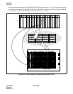
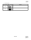
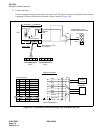
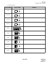
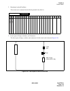
3. Face Layout of Lamps, Switches, and Connectors
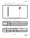
The face layout of lamps, switches, and connectors is shown in Figure 2-47.
Figure 2-47 Face Layout of the PH-PC45 (EMA) Card
Mounting Module
LPM
LPM
PH-IO24 (IOC)
PH-PC40 (EMA)
00 01 02 03 04
OPE/MB
MB
ACT1
CKERR1
ACT0
EMASUP
EMASUP
CPU SEL
NMI SEL
CKERR0
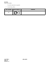
SW65
SW62
SW73
SW70
SW92
SW A0