


CHAPTER 3 NDA-24296
Page 396
Revision 1.0
PA-M69
Power Failure Transfer
6. External Interface
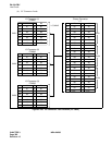
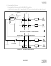
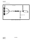
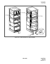
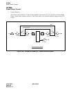
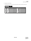
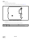
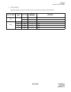
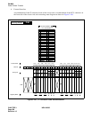
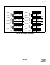
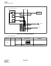
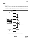
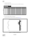
Accommodation of the LT connector leads of this circuit card, accommodation of the NCU connector on
the front side of the circuit card, and connecting route diagram are shown in Figure 3-106.
Figure 3-106 LT Connector Leads Accommodation
PIM
Mounting Module
232221201918171615141312111009080706050403020100
LT6 LT7 LT8 LT9 LT10 LT11LT0 LT1 LT2 LT3 LT4 LT5
231915
221814
211713
201612
231915
221814
211713
201612
110907050301
100806040200
110907050301
100806040200
Group No.
Slot No.
LT Connector
PIM
26
27
28
29
30
31
32
33
34
35
36
37
38
39
40
41
1
2
3
4
5
6
7
8
9
10
11
12
13
14
15
16
42
43
44
45
46
47
48
17
18
19
20
21
22
23
49
50
24
25
KY1
KY3
KY0
Accommodated in 1
LT 0, 6 Connector
KY2
KY4
KY6
KY5
KY7
1 1
HW11HW10HW9HW8HW7HW6HW5HW4HW3HW2HW1HW0
Highway Block