


CHAPTER 2 NDA-24296
Page 100
Revision 1.0
PH-PC36
Multiplexer
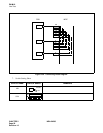
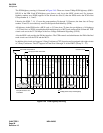
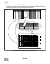
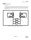
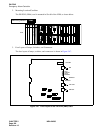
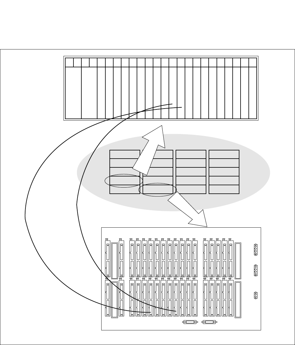
The cable connections between the MUX and the TSW are illustrated in Figure 2-43. As seen in this illustration,
the cable connected to the front of the MUX leads to the “MUX###” connector on the Back Wired Board (BWB)
of the TSWM. See the NEAX2400 IPX Installation Manual for more details.
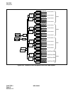
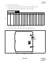
Figure 2-43 Cable Connections between the MUX and the TSW
00 01 02 03 04 05 06 07 08 09 10 11 12 13 14 15 16 17 18 19 20 21 22 23
PH-PC36(MUX)
PH-PC36(MUX)
PIM 3
PIM 2
PIM 1
PIM 0
Dummy
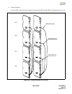
IMG3
PIM 3
PIM 2
PIM 1
PIM 0
Dummy/APM
IMG2
PIM 3
PIM 2
PIM 1
PIM 0
TSWM
IMG1
PIM 3
PIM 2
PIM 1
PIM 0
LPM
IMG0
PIM
BWB of TSWM