


NDA-24296 CHAPTER 3
Page 203
Revision 1.0
PH-CK16-A
Phase Lock Oscillator
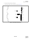
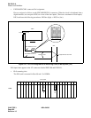
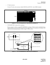
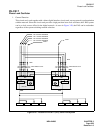
• LT cable connectors
Connect LT cables to the connectors labeled EXCLK0 and EXCLK1 on the ISWM backplane.
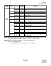
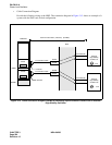
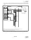
Figure 3-14 PLO Pin Assignment for Receiving Clock (ISWM) (1/2)
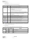
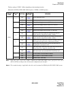
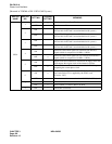
• EXCLK0/EXCLK1 connector Pin Assignment
Pins are assigned as follows on the EXCLK0/EXCLK1 connectors. When the clock is distributed from a
digital interface, use one pair of DIUxxx in one of four inputs. (There are a maximum of four inputs.) DIU
leads have the following precedence: DIU0xx (high) → DIU3xx (low).
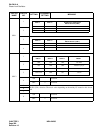
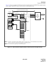
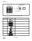
Figure 3-14 PLO Pin Assignment for Receiving Clock (ISWM) (2/2)
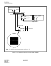
EXCLK1
EXCLK0
Backplane
ISWM
MDF
To Digital Interface and/or DCS
Installation Cable
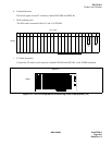
ISWM
EXCLK0
(Slot No.09)
EXCLK1
(Slot No.13)
34PH ISWM EXCLK CA-A
34PH ISWM EXCLK CA-A
Rear View
26
27
28
29
30
31
32
33
34
35
36
37
38
1
2
3
4
5
6
7
8
9
10
11
12
13
FM1
FM0
DIU3B
DIU2B
DIU1B
DIU0B
DCSB
SYN1B
SYN0B
E
E
DIU3A
DIU2A
DIU1A
DIU0A
DCSA
SYN1A
SYN0A