


NDA-24296 CHAPTER 3
Page 381
Revision 1.0
PA-24LCBV
Line Circuit
PA-24LCBV
Line Circuit
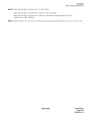
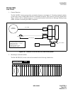
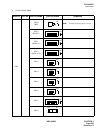
1. General Function
The PA-24LCBV circuit card provides an interface between a maximum of 24-analog terminals and the
system with a range of 600 (Ohm) inclusive of terminal resistance. This card also can send “Stutter Dial
Tone,” which is not a continuous tone, to an associated terminal which has no Message Waiting Lamp
(MWL) instead of activating the MWL if required.
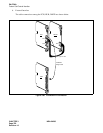
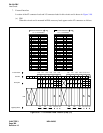
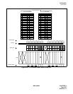
Figure 3-97 Location of PA-24LCBV (LC) Card in the System
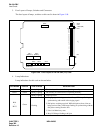
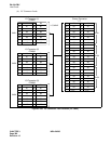
2. Mounting Location/Condition
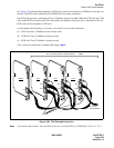
The PA-24LCBV(LC) circuit card can be mounted in the following shaded slots.
max. 600 [Ω]
Analog Terminal
COT
LC
INT SW
CPU GT
I/O Local Bus
(PA-24LCBV)
C. O. LINE
• Loop Resistance : Max 600[Ω]
(inclusive of terminal resistance)
• Reverse Function : x 1 circuit
• Stutter Dial Tone
• Message Waiting Lamp
• Encoding Law : µ-law
PUBLIC
NETWORK
00 01 02 03 04 05 06 07 08 09 10 11 12 13 14 15 16 17 18 19 20 21 22 23
PIM
Mounting Module