


NDA-24296 CHAPTER 2
Page 45
Revision 1.0
PH-GT10
Input Output Gate
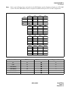
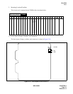
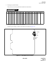
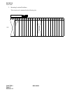
2. Mounting Location/Condition
This circuit card can be mounted in the shaded slots shown below.
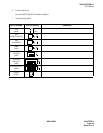
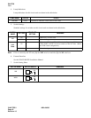
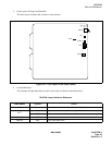
3. Face Layout of Lamps, Switches, and Connectors
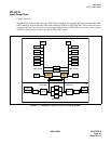
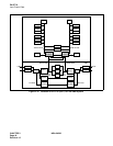
The face layout of lamps, switches, and connectors are shown in Figure 2-13.
Figure 2-13 Face Layout of PH-GT10 (IOGT)
Mounting Module
ISWM
00 01 02 03 04 05 06 07 08 09 10 11 12 13 14 15 16 17 18 19 20 21 22 23
MB
MBR
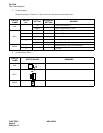
OPE/MB
PWRALM
CA4L
COPY