


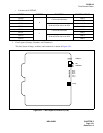

NDA-24296 CHAPTER 2
Page 131
Revision 1.0
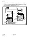
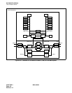
PH-SW12
Time Division Switch
• For the card in TSWM1
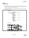
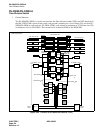
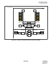
3. Face Layout of Lamps, Switches, and Connectors
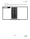
The face layout of lamps, switches, and connectors is shown in Figure 2-61.
Figure 2-61 Face Layout of PH-SW12 (TSW)
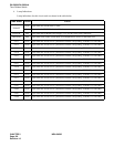
SYMBOL SYSTEM FUNCTION CONTROLLED IMG
TSW00
0
Collects the PCM data
IMG 2
TSW01 IMG 3
TSW02
Sends the PCM data to the ISW
IMG 2
TSW03 IMG 3
TSW10
1
Collects the PCM data
IMG 2
TSW11 IMG 3
TSW12
Sends the PCM data to the ISW
IMG 2
TSW13 IMG 3
MB
TSWMBR
TSWACT
M3SY
M2SY
M1SY
M0SY
PLO 1
PLO 0
TONE