


CHAPTER 2 NDA-24296
Page 32
Revision 1.0
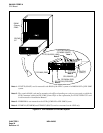
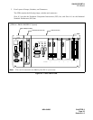
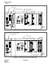
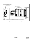
SN1695 CPRBF-A
CPU Board
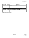
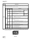
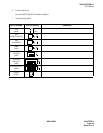
Note:
The segment spinning indication shows a processing status has completed successfully, or indicates “E”
meaning the processing failed.
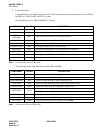
LAMP
NAME
DESCRIPTION
STATUS
(DSP)
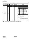
Two sets of “7-segment LED” show the CPR processing status. The CPR processing status is determined by the
SENSE switch settings, and the new processing status starts when the CPURST switch is pressed. The 7-segment
LED indication on each CPR processing status is listed below.
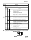
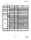
SENSE
STATUS
DESCRIPTION
LEFT RIGHT
0
“0-9”“0-9”
1. On-line active CPR
The active CPR which is in ON LINE status indicates the
CPU occupancy rate by percentage. (00-99%)
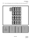
When the “EMA
SUP” switch is
“OFF” on the PH-
PC43 (EMA) card.
Not used
“S”
“b”
“y”
2. On-line stand-by CPR
The stand-by CPR which is in ON LINE status indicates
“S,” “b,” “y”
Not used “0-F”
3. Both active and stand-by CPR
The setting of SENSE switch is indicated.
When the “EMA
SUP” switch is
“ON” on the PH-
PC43 (EMA) card.
Not used
4. Program & Office data load
“1” indicated during the Program and Office data transfer from the HD to the
memory
“0” indicated during the Office data load
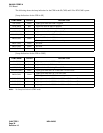
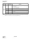
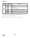
1
Not used
“F”
“c”
“d”
1. When Program Install
The HD in the CPR is initialized and the program is installed. (These three process-
es execute)
“F” indicated during HD format.
“c” indicated when copying data from FD (Basic Software #1) to HD
“d” indicated while making the directory on the HD
Not used “1”
2. When Program Load
After program installation, the program should be transferred from the HD to
memory.
“1” is indicated during this process.
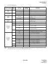
3Not used “c”“c” indicated when copying the data from FD to HD
5Not used
The CPR is starting-up with ON LINE (OAI memory clear restart).
“1” indicated during the Program load.
“0” indicated during the process.
CNot used “H”
The CPR is starting-up OFF LINE.
“H” indicated during the ROM data loading.
“1”
“0”
“1”
“0”
Segment Spinning In
d