


CHAPTER 2 NDA-24296
Page 168
Revision 1.0
PZ-PC23
Local Area Network Interface
2. Mounting Location/Condition
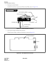
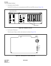
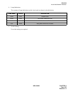
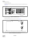
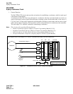
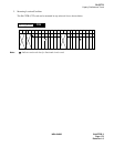
The PZ-PC23 (LANI) card is accommodated on the PCI bus Slot No.0 and No.3 in the CPR of SP as shown
in Figure 2-92.
Figure 2-92 Location for PZ-PC23
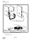
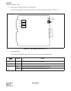
3. Face Layout of Connectors
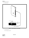
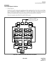
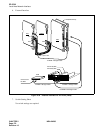
The face layout of lamps, switches, and connectors are shown in Figure 2-93.
Figure 2-93 Face Layout of PZ-PC23 (LANI) Card
5.0
A
PCI bus ISA bus
PZ-PW92
DC-40V -58.6
I
O
SW
ON
OFF
ON
ALM
PALM
OUTPWR
INPWR
5A
125V
AC/DC
CPUOPE WDT IMG0
IMG1
IMG2
IMG3
PZ-PC23
SP-CPR
100M0
TXRX0
LINK0
COL0
LAN0
Note
Note
100M1
TXRX1
LINK1
COL1
LAN1
Note:
Connect the Ether cable to “LAN0” connector for Processor bus within the IPX-UMG system. When
Fusion network is used, connect the Ether cable to “LAN1” connector to establish Fusion link.