


NDA-24296 CHAPTER 3
Page 371
Revision 1.0
PA-FCHA
Fusion Call Control Handler
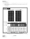
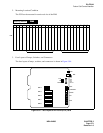
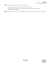
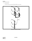
2. Mounting Location/ Condition
The FCH can be mounted in a universal slot of the PIM.
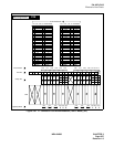
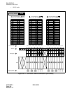
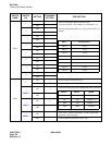
3. Face Layout of Lamps, Switches, and Connectors
The face layout of lamps, switches, and connectors is shown in Figure 3-94.
Figure 3-94 Face Layout of PA-FCHA (FCH) Card
00 01 02 03 04 05 06 07 08 09 10 11 12 13 14 15 16 17 18 19 20 21 22 23
PIM
Mounting Module
PIM
PIM
Universal Slots
Universal Slots
MB
OPE
EST3
EST2
EST1
EST0
PWALM
LYR
LB
LOAD
MNT
10-BASE-T
MODE
DTI
FCH
1 2 3 4 5 6 7 8
1 2 3 4
1 2 3 4 5 6 7 8
1 2 3 4 5 6 7 8
1 2 3 4 5 6 7 8
SW14
SW13
SW12
SW11
SW10