


CHAPTER 2 NDA-24296
Page 158
Revision 1.0
PZ-ME44
PCI Memory
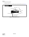
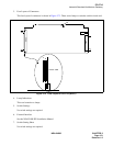
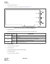
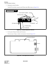
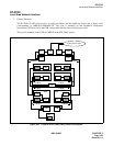
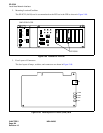
3. Face Layout of Connectors
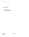
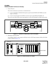
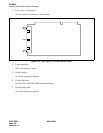
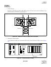
The face layout of connectors and lamps is shown in Figure 2-82.
Figure 2-82 Face Layout of PZ-ME44 (PCI MEM) Card
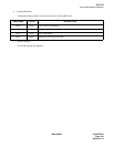
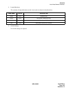
4. Lamp Indications
The contents of lamp indications on this circuit card are shown in the table below.
5. Switch Settings
No switch settings are required.
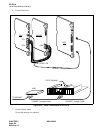
6. External Interface
See the NEAX2400 IPX-UMG Installation Manual.
7. Switch Setting Sheet
No switch settings are required.
LAMP NAME COLOR DESCRIPTION
COPY
Green Copy mode
OFF Self mode
SOFT
Green Normally operating in copy mode (Valid when “copy” lamp lights)
OFF Remains OFF during ACT → STBY memory copy
WE Green Lights when Memory writing
CONN
COPY
SOFT
WE