


CHAPTER 2 NDA-24296
Page 64
Revision 1.0
PA-PW55-A
Power
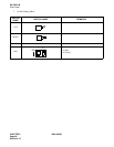
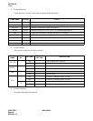
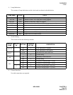
4. Lamp Indications
Lamp indications for this circuit card are shown in the table below.
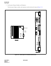
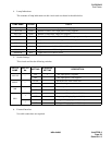
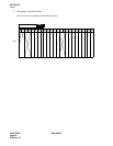
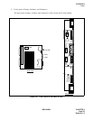
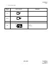
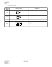
5. Switch Settings
This circuit card has the following switches.
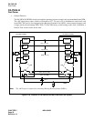
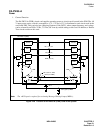
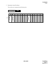
6. External Interface
No cable connections are required.
LAMP NAME COLOR STATE
+80V ON Green Remains lit while +80 V input power is being supplied.
–48 V ON Green Remains lit while –48 V input power is being supplied.
RGU ON Green Remains lit while RGU output is in progress.
DC ON Green Remains lit while +5 V, +12 V, and –5 V are being output normally.
OPE Green Lights when information exchange with the CPU is possible.
CPUALM Red Lights when reset of the microprocessor has been activated.
DCALM Red Lights when +5 V, +12 V, or –5 V outputs alarm.
RGUALM Red Lights when RGU voltage alarm.
HOWALM Red Lights when howler alarm.
SWITCH
NAME
SWITCH
No.
SETTING
STANDARD
SETTING
DESCRIPTION
–48 V SW
ON × –48 V input power is supplied.
OFF –48 V input power is not supplied.
RESET
PUSH Hardware reset of the circuit card.
— × Normal setting
MB —
ON Make-busy of the circuit card.
OFF × Normal setting
SW4
1
ON Frequency of Ringing Signal :25 [Hz]
OFF × Frequency of Ringing Signal :20 [Hz]
2
ON × Voltage of Ringing Signal: 90 [Vrms]
OFF Voltage of Ringing Signal: 75 [Vrms]