


NDA-24296 CHAPTER 3
Page 379
Revision 1.0
PA-FCHA
Fusion Call Control Handler
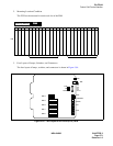
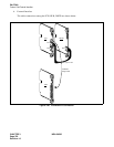
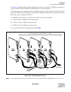
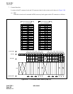
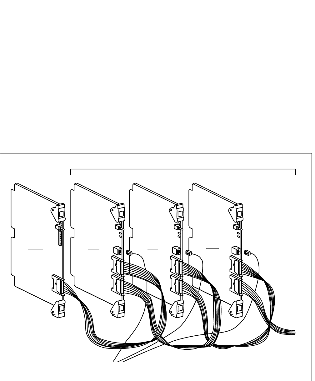
See Figure 3-96 when multiple numbers of FCH circuit cards are connected to a 24DTR as a cascade con-
nection. The FCH can be combined with CCH/DCH on a cascade connection.
One DTI card can have a maximum of five (5) Handler circuits cascaded within the FCH card, the CCH
card, and/or DCH card. Since the FCH card contains one Handler circuit per card, a maximum of five (5)
FCH cards can be cascaded to a DTI card.
As an example, the following (a), (b) and (c) can coexist on a cascade connection.
(a) FCH card (One (1) Handler circuit card per card)
(b) CCH card (Two (2) Handler circuits per card)
(c) DCH card (Two (2) Handler circuits per card)
Also, you must consider the cascading cable length. (
Note
)
Figure 3-96 FCH Cascade Connection
Note:
A maximum cable distance between DTI and the last cascaded FCH (or CCH/DCH) is 50 cm (1’ 7.6 ”).
24DTR FCH FCH FCH
Max. 5 handling circuits of FCH/CCH/DCH Note
To the next
FCH/CCH/DCH
CN2
DTI
FCH
DTI
FCH
DTI
FCH
To HUB