


CHAPTER 2 NDA-24296
Page 110
Revision 1.0
PH-PC45
Emergency Alarm Controller
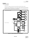
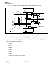
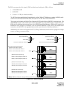
6. External Interface
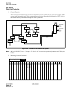
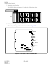
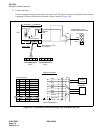
External equipment may be connected to this circuit card. The physical connection diagram for the external
equipment for Music-On-Hold and External Alarm is shown in Figure 2-48.
Figure 2-48 Connection of Alarm Indicating Panel and Music on Hold
01 02 03 04 0501 02 03 04 05
26
27
28
29
30
31
32
33
34
E
E
-
MJB
MNA
-
1
2
3
4
5
6
7
8
9
FM0
FM1
MPALM
MJA
MNA
BELL
50
EXTA EXTB
25
16PH EXALM CA
FM0
E
MJA
MNA
BELL
MJB
MNB
RPT1(G)
RPT0(-48V)
CABLING DIAGRAM
CROSS CONNECTION
MDF
EXTERNAL
MUSIC
SOURCE
MJ/MN/BELL
-48V
(RPT0)
G
(RPT1)
AUDIBLE AND VISUAL
ALARM INDICATING PANEL
MDF
MJ
MN
BELL
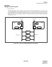
EALM Connector
EMA
(Slot No.04)
16PH EXALM CA
(BASEU)
LPM
Installation
Cable
RPT Terminal on front
of the BASEU
REAR VIEW