


CHAPTER 3 NDA-24296
Page 418
Revision 1.0
PA-8RSTM
Register Sender Trunk
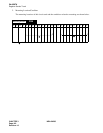
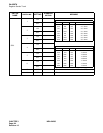
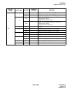
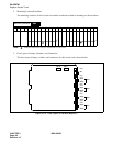
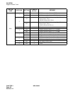
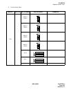
2. Mounting Location/Condition
The mounting locations for this circuit card and the conditions related to mounting are shown below.
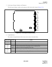
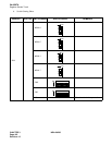
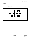
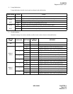
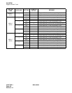
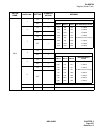
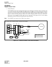
3. Face Layout of Lamps, Switches, and Connectors
The face layout of lamps, switches, and connectors for this circuit card is shown below.
Figure 3-118 Face Layout of PA-8RSTM (8RST)
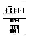
00 01 02 03 04 05 06 07 08 09 10 11 12 13 14 15 16 17 18 19 20 21 22 23
Note:
Indicates universal slots for line/trunk circuit cards.
Mounting Module
PIM
OPE
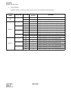
MB
BLS7
BLS4
MBS7
MBS4
BLR7
BLR4
MBR7
MBR4
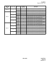
BLS3
BLS0
MBS3
MBS0
BLR3
BLR0
MBR3
MBR0
SW11
~
~
~
~
~
~
~~
SW10
SW04
SW03
SW02
SW01