


CHAPTER 3 NDA-24296
Page 180
Revision 1.0
PA-CK14
Oscillator
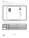
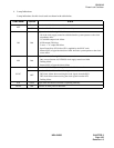
4. Lamp Indications
Lamp indications for this circuit card are shown in the table below.
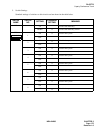
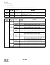
5. Switch Settings
Standard settings for switches on this circuit card are shown in the table below.
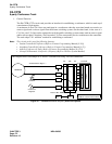
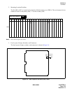
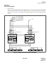
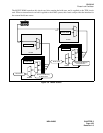
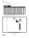
6. External Interface
Since the base clock signals are delivered through the printed-wiring on the Back Wired Board (BWB) of
PIM 0, this circuit card does not require any external cabling.
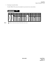
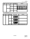
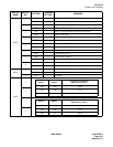
7. Switch Setting Sheet
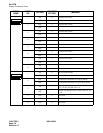
LAMP NAME COLOR STATE
CLKOUT0 Green Lights when OSC card delivers the clock signals to TSW#0.
CLKOUT1 Green Lights when OSC card delivers the clock signals to TSW#1.
SWITCH
NAME
SETTING
STANDARD
SETTING
MEANING
MB
ON Make-busy of the circuit card.
OFF × Normal setting.
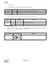
SWITCH NAME SWITCH SHAPE REMARKS
MB
ON