


CHAPTER 3 NDA-24296
Page 590
Revision 1.0
PA-24PRTB-A
Primary Rate Interface Trunk
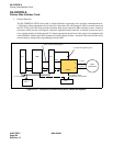
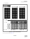
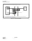
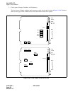
Figure 3-184 Connecting Route Diagram
RA
RB
TA
TB
POUTA
POUTB
RA
TA
TB
RB
DIU1A
DIU1B
PLO
PBX
MDF
clock extraction
24 PRT
To DSU
(Digital
Service
Unit)
Note
IN
OUT
Connecting Route Diagram for the PA-24PRTB-A circuit card is as follows.
Note:
As an example, DIU1A and DIU1B leads are used in this diagram. For more information on
the PLO card, see Chapter 2 in this manual.