


NDA-24296 CHAPTER 3
Page 505
Revision 1.0
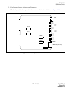
PA-4ILCH
ISDN Line Circuit
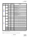
Note 1:
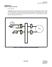
The terms Point-to-Point (P-P) and Point-to-Multipoint (P-mP) used in this table have no relation to the
actual wiring configuration.
Note 2:
This switch must be set according to the specification of the ISDN terminal.
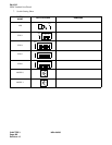
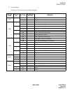
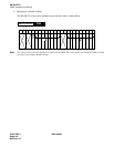
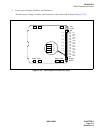
SWITCH
NAME
SWITCH
NO.
SETTING
STANDARD
SETTING
MEANING
SW20
Note 1
Note 2
1
ON
Data link mode for Layer 2 of line 0:
Point-to-Multipoint (P-mP)
OFF
Data link mode for Layer 2 of line 0:
Point-to-Point (P-P)
2
ON
Data link mode for Layer 2 of line 1:
Point-to-Multipoint (P-mP)
OFF
Data link mode for Layer 2 of line 1:
Point-to-Point (P-P)
3
ON
Data link mode for Layer 2 of line 2:
Point-to-Multipoint (P-mP)
OFF
Data link mode for Layer 2 of line 2
Point-to-Point (P-P)
4
ON
Data link mode for Layer 2 of line 3:
Point-to-Multipoint (P-mP)
OFF
Data link mode for Layer 2 of line 3:
Point-to-Point (P-P)
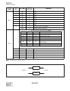
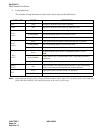
SW21
Note 2
1
ON On line 0, Layer 1 of S Reference Point is activated on a call basis.
OFF On line 0, Layer 1 of S Reference Point is always activated.
2
ON On line 1, Layer 1 of S Reference Point is activated on a call basis.
OFF On line 1, Layer 1 of S Reference Point is always activated.
3
ON On line 2, Layer 1 of S Reference Point is activated on a call basis.
OFF On line 2, Layer 1 of S Reference Point is always activated.
4
ON On line 3, Layer 1 of S Reference Point is activated on a call basis.
OFF On line 3, Layer 1 of S Reference Point is always activated.
5ON
×
Fixed
6ON
×
Fixed
7ON
×
Fixed
8ON
×
Fixed