


NDA-24296 Chapter 3
Page 171
Revision 1.0
CHAPTER 3 LINE/TRUNK CIRCUIT CARD REFERENCE
1. GENERAL
This chapter explains the following items about circuit cards.
• General Function
Explains the general function and purpose for each control circuit card.
• Mounting Location/Condition
Explains the mounting location (mounting module name and slot number, etc.) of each circuit card. If there
are any conditions pertaining to mounting the circuit cards, they are also explained.
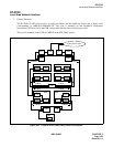
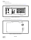
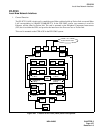
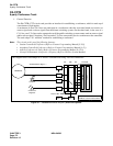
• Face Layout of Lamps, Switches, and Connectors
The locations of the lamps, switches, and connectors provided on each circuit card are illustrated by a face
layout.
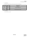
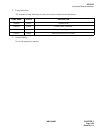
• Lamp Indications
Names, colors, and indication states of lamps mounted on each circuit card are listed.
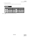
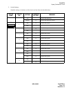
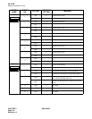
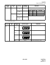
• Switch Settings
Each circuit card’s switches are listed with their names, switch numbers, setting and its meaning, standard
setting, etc.
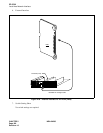
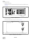
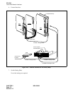
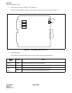
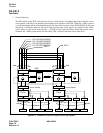
• External Interface
If the lead outputs of the circuit card are provided by an LT connector, the relation between the mounting
slots and the LT connectors is illustrated by an LT Connector Lead Face Layout. If the lead outputs are
provided by other than an LT connector, or are provided by the circuit card front connector, the connector
lead locations and the connecting routes are shown.
In addition, a Switch Setting Sheet is provided at the end of the explanation of circuit cards.