


CHAPTER 3 NDA-24296
Page 466
Revision 1.0
PA-24CCTA
Common Channel Trunk
3. Face Layout of Lamps, Switches, and Connectors
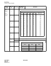
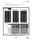
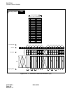
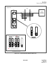
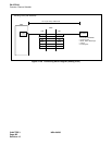
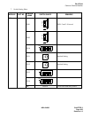
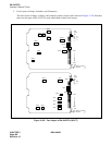
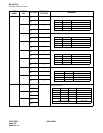
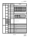
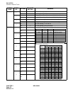
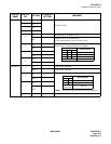
The face layout of lamps, switches, and connector on this circuit card is shown in Figure 3-138. Note that
there are two types of PA-24 CCTA cards which differ in their face layouts.
Figure 3-138 Face Layout of PA-24CCTA (24CCT)
3
2
1
0
SW6G
SW5DSW4D
SW6C
SW39
SW58
SW25
SW11B
SW138
SW13B
MODE
OPE
N-OPE
MB
PCM
BER
AIS
DOPE
LB
FRM
RMT
LYR
BL23
BL00
CN2
To "TRK" Connector
on CCH/DCH
3
2
1
0
SW18
SW19
SW15 SW14
SW13
OPE
N-OPE
MB
PCM
BER
AIS
DOPE
LB
FRM
RMT
LYR
BL23
BL00
CN2
To "TRK" Connector
on CCH/DCH
SW17
SW00
SW01
SW02
SW12
SW11
SW10