


NDA-24296 CHAPTER 3
Page 235
Revision 1.0
PH-CK17-A
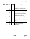
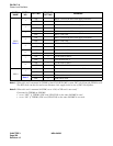
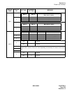
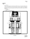
Phase Lock Oscillator
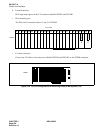
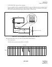
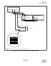
Figure 3-32 LT Connector Lead Location of PLO (ISWM-TSWM0/1)
CLK00
(Slot No.08)
CLK10
(Slot No.12)
TSWM1
TSWM0
ISWM
Installation Cable
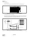
DIU Connection Note
MDF
To Digital Interface
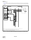
EXCLK0
(Slot No.21)
PLO CLOCK0
(Slot No.21)
EXCLK1
(Slot No.23)
PLO CLOCK1
(Slot No.23)
PLO CLOCK0
(Slot No.21)
PLO CLOCK1
(Slot No.23)
ISW-LN PLO CA-A
PLO-CLK CA-A
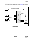
DCS Connection
Note:
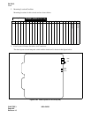
For DIU connection route diagram, see the figure on the next page.
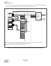
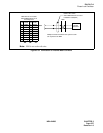
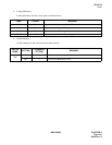
26
1
LEAD
NAME
LEAD
NAME
27
2
28
3
PIN
No.
PIN
No.
29
4
30
5
FM1
FM0
31
6
32
7
33
8
34
9
35
10
E
DIU 3B
DIU 2B
DIU 3A
DIU 2A
E
DIU 1B
DIU 1A
DIU 0B
DIU 0A